Table of Contents
Advertisement
Quick Links
Advertisement
Table of Contents

Related Manuals for PackshotCreator PackshotCompact


Summary of Contents for PackshotCreator PackshotCompact
- Page 1 PackshotCompact QuickStart I N S T A L L A T I O N G U I D E...
- Page 2 1 USB cable © Sysnext. All rights reserved. This material is not to be interpreted as a guarantee of earnings and may not be copied, reproducved, modified, published, uploaded, posted or distributed in any way, without PackshotCreator’s prior consent.
-
Page 3: Specifications
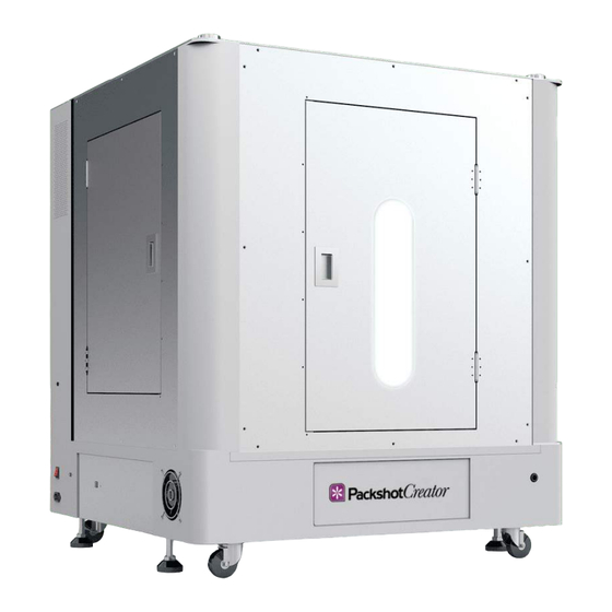
PackshotCompact SPECIFICATIONS Dimension (L x W x H): 100cm x 100cm x 120cm Maximum Target Size Top Shots: 56cm x 56cm Side Shots: 56cm x 56cm x 80cm Total Weight: 100 kg Maximum Object Weight: 20.4 kg CONTACT INFO: Email: help@packshot-creator.com... -
Page 4: System Placement
PackshotCompact SYSTEM PLACEMENT ROLLING THE UNIT: When all legs are up, roll the unit Use the #24 wrench to adjust leg Rotate the bottom nut to raise or into position. Lower the legs, height. Start by loosening the top lower the leg. - Page 5 Place the system on the floor. Make Place the system on (Optional): (Optional): an PackshotCreator ErgoTable+ sure the system is level and legs an PackshotCreator ErgoTable (sold (sold separately). are locked into position. separately). Place the system on Any external lighting, such as...
-
Page 6: Hardware Installation
PackshotCompact HARDWARE INSTALLATION ACRYLIC PANEL INSTALLATION 1/2: Remove the five white hand Remove the two white hand screws Remove the top light panel from screws. holding the top light panel to the the top by sliding it to the left and top. - Page 7 PackshotSpin Align the acrylic panels when the front door is detached. Note: O3T inside the PackshotCompact, between the metal guide brackets Insert the acrylic panels between so the power and USB cables can on the top, before tightening.
-
Page 8: Cable Connection
Instead of batteries, remote capture capabilities, (Optional): we recommend using an AC power PackshotCompact can supply a adapter to power your camera. custom shutter release cable to connect the camera to the system so software can automate image... - Page 9 PackshotCompact HARDWARE INSTALLATION CABLE CONNECTION 2/2: Respectively, plug one end of the In this configuration, captured If you are using camera top shot, USB Type A cable into the left side images are saved to the memory plug the USB cable from your of the back light panel and the card.
- Page 10 PackshotCompact HARDWARE DISASSEMBLY SURROUNDING COVERS REMOVAL: Lift to remove both side walls and Unplug the studio and the top light Follow instructions from steps front door. power cable. in the “Acrylic Panel Installation” part of this document to remove the top and top light, and then remove the acrylic panels if any.
- Page 11 PackshotCompact HARDWARE DISASSEMBLY FRONT LIGHT COLUMNS REMOVAL: Remove the hand screw. Lift to remove the diffusion plate. Disconnect the connector for the The hex socket button LED lamps. Note: screws do not need to be removed. Lift to remove the column.
- Page 12 PackshotCompact HARDWARE DISASSEMBLY BACK AND BOTTOM LIGHT PANELS SEPARATION: Remove six white hand screws, Unplug the two metal connectors. Unplug the power connector. three on each side. Slide the back light panel away The back light panel is very Once the two panels are...
- Page 13 PackshotCompact HARDWARE DISASSEMBLY BOTTOM GLASS PLATE REMOVAL: Slide to remove the bottom Use a Phillips screwdriver to Remove the holding bracket. background and glass plate from remove two screws and the the system. holding bracket on the front end of...
Need help?
Do you have a question about the PackshotCompact and is the answer not in the manual?
Questions and answers