Advertisement
Optional
q
Recommended
q
3
Mandatory
q
DATE:
MODEL:
REVISION:
SERIAL NO:
SOFTWARE:
DESCRIPTION:
There are three PROMs in the System Unit. A software upgrade may require replacement of either the
machine or control PROMs. Replace only the PROMs that were shipped to you.
Look at the PROM(s) in the shipping container. The Software Version number is listed on the PROM
label; the number is preceded by MC or CP. Micro Lynx uses two MC (Machine Control) and one CP
(Control Processor) PROM. Both MC PROMs must be replaced at the same time, do not replace only one!
Record the serial numbers and software version in the front of your Micro Lynx Manual, they are
required to receive assistance from Customer Service.
REQUIRED TOOLS:
PROCEDURE:
1. Turn off the power and disconnect all
power cables.
2. Place the Micro Lynx System Unit on a
static safe workstation. Ground yourself and the workstation anti-static mat.
3. Remove the six phillips screws securing
the top cover to the chassis. Turn the
System Unit so that the front panel faces you and remove the top cover.
ECC 294
System Unit PROM Installation
06/12/92
Micro Lynx
All
All
Machine Control PROM
Control PROM
Static safe workstation
IC Extractor/Insertor
or small screwdriver
PROM Installation Guide
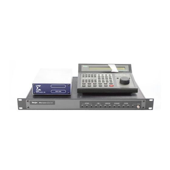
Micro Lynx System Unit (SU)
U51
U47
U4
Grounding wrist strap
Phillips screwdriver
Page 1
TIMELINE VISTA, INC.
1755 LA COSTA MEADOWS DRIVE, SUITE B
SAN MARCOS, CA 92069
TEL. 760-761-4440
(FAX 760-761-4449)
SUPPORT@DIGAUDIO.COM
73J008 REV A
Advertisement
Table of Contents

Related Manuals for TimeLine Micro Lynx System Unit


Summary of Contents for TimeLine Micro Lynx System Unit
- Page 1 PROCEDURE: 1. Turn off the power and disconnect all power cables. 2. Place the Micro Lynx System Unit on a static safe workstation. Ground yourself and the workstation anti-static mat. 3. Remove the six phillips screws securing the top cover to the chassis. Turn the System Unit so that the front panel faces you and remove the top cover.
- Page 2 Figure 1. Open the Top Cover PROM Installation Guide 4. Locate and replace the appropriate PROMs. Remember to align pin 1 on the PROM with pin 1 in the socket. All PROMs have a small cutout at one end which indicates the location of pin 1. The printed circuit board also has a cutout mark at one end of each IC to indicate orientation.
- Page 3 Figure 2. System Unit PROM Locations 5. Replace the cover on the System Unit. Insert and tighten the 6 phillips screws. Reconnect the cables and turn on the power. The System Unit will sense the new software and boot correctly. To verify that the upgraded software is operating, press SYS on the Keyboard Unit, the new software version numbers will be displayed.
Need help?
Do you have a question about the Micro Lynx System Unit and is the answer not in the manual?
Questions and answers