Table of Contents
Advertisement
Quick Links
Advertisement
Table of Contents

Related Manuals for InWin IW-RS436-07


Summary of Contents for InWin IW-RS436-07
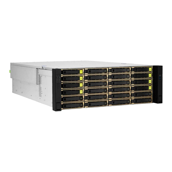
- Page 1 IW-RS436-07 User Manual 4U NVMe Hybrid Storage Server...
-
Page 2: Safety Information
InWin’s server website. SAFETY INFORMATION To ensure a safe and smooth operation of your InWin IW-RS436-07, it is essential that you choose an appropriate location for the system, provide an appropriate operating environment and supply an adequate amount of power for all components of the system. - Page 3 Installing or Removing Jumpers: A jumper is a short length conductor used to close, open or bypass part of an electronic circuit. Jumpers on InWin backplanes have a small tab on top that you can pick up with your fingertips. Grip the jumper carefully and plug the jumper to cover the jumper pins on the backplane.
-
Page 4: Product Introduction
1 Product Introduction 1.1 Box Contents When you open the IW-RS436-07 box, the contents should include following:... -
Page 5: Accessories Box
1.2 Accessories Box Item Item Label x 1 Power LED 3-pin to 2-pin Adapter x 1 Motherboard Stand-off Sockets and Cable Ties-1 x 5 Screws x 12 Cable Ties-2 x 6 2.5" HDD Screws x 108 Jumper for HDD Backplane x 2... -
Page 6: General Information
1.3 General Information When you open the chassis, it should reflect the diagram’s image. Top cover USB 3.0 x 2 Top cover screwless open button Slide rail mounting area Front backplane ATX, CEB, EEB M/B mounting area Rear backplane 80 Plus Platinum CRPS (including PDB) 80 x 38mm PWM hot-swap top fans x 4 Rear 2.5"... -
Page 7: Front Panel Controls And Indicators
1.3.1 Front Panel Controls and Indicators The IW-RS436-07 supports either 2.5"/3.5" SAS/SATA disk bays x 36 or 2.5"/3.5" SAS/SATA disk bays x 24 and NVMe x 12 disk bays in specific areas. The control panel, USB I/O ports and indicators are located on the handles. -
Page 8: Rear Panel Configuration
Power Module 1 Default primary power supply module. Power Module 2 Backup power supply module. This slot is for InWin OS disk backup module which supports two 2.5" OS HDD 12G SSDs and features hot-swap function. System I/O The I/O shield should come with the motherboard or is provided by (Depends on M/B Specifications) motherboard vendors. -
Page 9: Hardware Installation
07 Series Motherboard & Expansion Card. For a quick installation video, please visit HDD Tray Installation The IW-RS436-07 features tool-less trays. Users no longer need to use screws to mount disks, and can swap drives faster. 07 Series HDD Tray Installation. - Page 10 ● 2.4.1 Power Supply Cable Information 300mm 24 pin main motherboard 330mm 8 pin CPU 435mm 12V 8pin front BP 435mm 12V 8pin front BP 635mm 12V 8pin rear BP 450mm 8 pin CPU 435mm 5V 6pin front BP 435mm 5V 6pin front BP 635mm 5V 6pin rear BP...
-
Page 11: Connecting Cables
2.5 Connecting Cables Connecting LED Cable, Front Control Panel and Front USB I/O Ports Refer to your motherboard user guide for pin functions and locations, and then plug the connectors to the pins on the motherboard to activate the functions. USB 3.0 LED Connector Connector Name... -
Page 12: Slide Rail Installation
2.6 Slide Rail Installation The IW-RS436-07 is a rackmount model, which supports EIA-RS310D standard cabinets and chassis racks. InWin provides standard slide rails to allow users to mount the chassis onto the cabinets. 2.6.1 Identifying the Slide Rail The slide rail by your order might be different. You can reference the quick installation guide inside the slide rail package and follow the instructions to mount the rail onto your cabinet or chassis rack. - Page 13 Step 3 2.6.4 Mounting the Rail Bracket to the Cabinet Step 1: Extend the rail bracket over the rear rack of the cabinet. Step 2: Pull out the rear hook on the end of the outer rail, align and push the rail bracket pins into the post holes on the rack.
-
Page 14: Inserting The Chassis To The Cabinet
2.6.5 Inserting the Chassis to the Cabinet Step 1: Pull out the middle rail to the stop position. Step 2: Move the ball bearing retainer to the front end of the middle rail, and it should click into the locked position. Step 3: Insert the inner rails of the chassis into the middle rails on both sides of the rack. -
Page 15: Backplane Introduction
3 Backplane Introduction InWin backplanes with expander onboard are high performance and are cost-effective solutions for supporting Intel® Xeon Scalable & AMD EPYC family by adding NVMe support. The active backplanes support state-of-the-art SAS3 12Gbps HDD/SSD and are also backward compatible with SAS 6Gbps, SATA 6Gps and SATA 3Gps HDD/SSD. - Page 16 Rear Host Side Port 2 Port 1 Port 3 Rear HDD Side 3.2 Slimline Backplane for NVMe Front Host Side Port 2 Port 1 Port 3 Front HDD Side...
-
Page 17: Connecting Expander Through Sas Connectors
Backplane Connection 3.3.1 Oculink and Slimline Backplane Connection The IW-RS436-07 supports NVMe SSDs through either Oculink x 12 or Slimline x 12 connectors, and these two independent backplanes equipped with expander onboard are backward compatible with Mini-SAS HD. 3.3.2 Connecting Expander Through SAS Connectors Use the SAS 8643 cable to connect the Expander to the motherboard. -
Page 18: Compatibility Lists
InWin’s chassis. You can download the latest updated device compatibility list from InWin’s website: ipc.in-win.com 5 Technical Support If you need help with installation or troubleshooting, you can contact your local InWin reps, or send an e-mail to InWin’s local contacts for technical assistance. - Page 19 Copy r i g ht © I n Wi n D evel o p m ent I n c . A l l Ri g ht s Res e r ved .
Need help?
Do you have a question about the IW-RS436-07 and is the answer not in the manual?
Questions and answers