Table of Contents
Advertisement
Quick Links
Advertisement
Table of Contents

Related Manuals for Amate Audio Xcellence X212AFD


Summary of Contents for Amate Audio Xcellence X212AFD
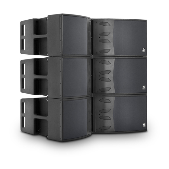
- Page 1 User’s manual X212AFD July 2021...
- Page 2 D. The equipment has been exposed to the rain; or E. The chassis is damaged 9. Disconnect the device in the case of electric storms or during long periods of disuse. 10. Never hang the equipment by its handle. 11. Only use manufacturer recommended accessories. Amate Audio...
-
Page 3: General Product Information
INTRODUCTION 1.1 General product information Amate Audio thanks you for the trust placed in our Xcellence loudspeaker systems. The Xcellence series combines the convenience of a self-powered system and the flexibility of the DSP (digital system processing) for cabinet control. More than 45 years’... - Page 4 This is achieved by using waveguides, which are coupled to the compression drivers output. We achieve flat wave fronts with a constant phase. By vertically assembling these waveguides we fulfil the second criterion of line array construction. Fig.2. Second criterion of "arrayability" Amate Audio...
- Page 5 (this is geometrically equivalent to shaping variable curvature arrays to provide equal spacing of individual element impact zones). • There are limits given the vertical size of each cabinet and their relative tilt angles. In our case the maximum tilt angle (between cabinets) is 8º. Amate Audio...
- Page 6 The limit distance between the zone of cylindrical waves (Fresnel) and spherical waves (Fraunhofer) can be calculated through the following formula: where, = limit distance between near field and far field (in metres) H = height of the array (in metres) Amate Audio...
- Page 7 In the first zone (Fresnel), sound pressure loss is only 3 dB per doubling of distance, whereas in the second zone (Fraunhofer) the loss is 6 dB. In long throw and high SPL configurations it is very important to produce cylindrical waves. Amate Audio...
- Page 8 • 2 x 12” neodymium woofers with 3” voice coil • 4 x 6” neodymium woofers with 1.5” voice coil coupled to 2 x mid phase plugs • 2 x 3” titanium diaphragm neodymium drivers coupled to 1 x HF waveguide • 100 x 8º dispersion Amate Audio...
-
Page 9: Technical Description
Polyurea paint coating. The front face is protected by two 1.5 mm thick steel grilles with acoustically transparent grey cloth. It includes two in-built lateral handles for an easy and comfortable transport. Amate Audio... - Page 10 Nearfield cabinets (the lower ones). The system operates over the nominal bandwidth of the X212AFD enclosure (42 Hz – 18 kHz, -10dB). Model: X212AFD Preset: [HPF60 LONGTHROW] [HPF60 FLAT] Model: X212AFD Preset: [HPF60 FLAT] Model: X212AFD Preset: [HPF60 NEARFIELD] [HPF60 NFIELD] Amate Audio...
-
Page 11: System Alignment
2.8m when the upper frequency limit of the subwoofer is at 60 Hz. SYSTEM ALIGNMENT The system is pre-aligned from the factory. Do not forget to add the geometric delay depending on the configuration used. Amate Audio... - Page 12 2.1m when the upper frequency limit of the subwoofer is at 80 Hz. SYSTEM ALIGNMENT The system is pre-aligned from the factory. Do not forget to add the geometric delay depending on the configuration used. Amate Audio...
- Page 13 2.8m when the upper frequency limit of the subwoofer is at 60 Hz. SYSTEM ALIGNMENT The system is pre-aligned from the factory. Do not forget to add the geometric delay depending on the configuration used. Amate Audio...
- Page 14 2.1m when the upper frequency limit of the subwoofer is at 80 Hz. SYSTEM ALIGNMENT The system is pre-aligned from the factory. Do not forget to add the geometric delay depending on the configuration used. Amate Audio...
-
Page 15: Control And Connection Panel
When signal is present again, the system will go automatically into normal mode. • Mute: (Red) The system is muted (amplifiers are disabled). The system can be muted from the PC remote control or from the touchscreen. Amate Audio... - Page 16 (DSPStudio) and for audio signal input via Dante audio networking. Please refer to Amate Audio DSPStudio Quick Installation Guide for more information on remote connection. The two connectors are interconnected by means of an internal switch, so they can be used interchangeably and allow the chain connection of several boxes.
-
Page 17: Parallel Connection
INPUT signal to the second unit and thus sequentially for further units. All of the units in this chain must be switched on. Fig.10. Parallel connection for the X212AFD (signal). You can link three units or more Amate Audio... - Page 18 When not, there is no specific limit for daisy-chaining (control and monitoring using DSPStudio®). Fig.11. Parallel connection for the X212AFD (network). You can link up to eight units when using Dante networking, or more when not using it. Amate Audio...
- Page 19 Do not connect more than three X212AFD units using the AC Mains link connector. Do not connect Xcellence series units in parallel using PowerCon-PowerCon without earth. Fig.12. Parallel connection for the X212AFD (mains). You can link up to three units Amate Audio...
- Page 20 5.2 Parallel connection with subwoofers You can connect the X212AFD in parallel with X218WFD subwoofers or other units. Please, follow the same parameters as explained in the following diagrams: Fig.13. Parallel connection for the X212AFD and X218WFD (signal) Amate Audio...
- Page 21 X212AFD July 2021 Fig.14. Parallel connection for the X212AFD and X218WFD (mains). Do not connect more than three units of X212AFD or two units of X218WFD using the AC Mains link connector. Amate Audio...
- Page 22 X212AFD July 2021 Fig.15. Parallel connection for the X212AFD and X218WFD (network). Do not daisy- chain more than eight units of each when using Dante networking (as in the diagram). Amate Audio...
-
Page 23: Overvoltage Protection
Do not fly systems from unsafe structures. All flying accessories that are not supplied by Amate Audio are the user's responsibility. Use at your own risk. Remember that no risks should be taken with regards to public safety. - Page 24 (I) to be attached to the X212AFD lateral rigging guides and one central lock hole (J) to be attached to the X212AFD back rigging guide. To safely lock the frame, the lock pins (K) and (L) supplied must be used. Fig.17. TA-X212 flying frame Amate Audio...
- Page 25 The numbers on the central bar are those corresponding to Ease Focus calculations. Fig.18. Pin points on TA-X212 7.2 Vertical Flying • On its “STORE” position, both the lateral rigging guides (left and right) and the back rigging guide are hidden and locked with their ball lock pins. Amate Audio...
- Page 26 • Release both the left and right ball lock pins of the first cabinet and let the inner guides go up. Then, block the guides by putting the ball lock pins. Fig.20. Release of the lateral rigging guides of X212AFD (first cabinet) Amate Audio...
- Page 27 Then, block the guide by putting the ball lock pin. First point the arrow to “FRAME” mark and then put the lock pin on “FRAME” hole. Fig.21. Release of the back rigging guide of X212AFD (first cabinet) Arrow: “FRAME” Pin hole: “FRAME” Fig.22. Arrow position and pin hole position (first cabinet) Amate Audio...
- Page 28 • Once the frame is received by the X212AFD lateral and back rigging guides, use the provided ball lock pins on the TA-X212 to attach the frame to the cabinet (pins A & B). Fig.24. TA-X212 attached to X212AFD (first cabinet) Amate Audio...
- Page 29 Then, block the guide by putting the ball lock pin. Point the arrow to the desired angle mark and then put the lock pin on the desired angle hole. Arrow mark 0º / Pin hole 0º Arrow mark 0.5º / Pin hole 0.5º Amate Audio...
- Page 30 X212AFD July 2021 Arrow mark 1º / Pin hole 1º Arrow mark 1.5º / Pin hole 1.5º Arrow mark 2º / Pin hole 2º Arrow mark 2.5º / Pin hole 2.5º Amate Audio...
- Page 31 X212AFD July 2021 Arrow mark 3º / Pin hole 3º Arrow mark 4º / Pin hole 4º Arrow mark 6º / Pin hole 6º Arrow mark 8º / Pin hole 8º Fig.26. Choose the desired tilting angle Amate Audio...
- Page 32 X212AFD July 2021 • Release the pins (E left), (E right) and (G back) from the first unit. Fig.27. Release pins (E) and (G) from first cabinet Fig.28. Release pins (E) and (G) from first cabinet Amate Audio...
- Page 33 (A1) on both left and right side. Put pins (E left and right) on holes (A-A1 left and right). Fig.29. Put pins (E) on holes (A-A1) • Align hole (B) and (B1). Insert pin (G) in hole (B-B1). Fig.30. Put pin (G) on hole (B-B1) Amate Audio...
- Page 34 July 2021 Fig.31. 0º, 0.5º, 1º between two X212AFD cabinets Fig.32. 1.5º, 2º, 2.5º between two X212AFD cabinets Fig.33. 3º, 4º, 6º between two X212AFD cabinets Fig.34. 8º between two X212AFD cabinets • For further units, proceed sequentially. Amate Audio...
-
Page 35: Mounting Accessories
X212AFD July 2021 MOUNTING ACCESSORIES 8.1 Stacking frame for X218WFD (FR-X212) The FR-X212 is an optional accessory for stacking the X212AFD with X218WFD. “FR-X212 user’s manual” more information. Fig.35. FR-X212 frame stacking Amate Audio... - Page 36 X212AFD July 2021 Fig.36. FR-X212 stacking system Amate Audio...
- Page 37 X212AFD July 2021 8.2 Frame Adaptor FA-X210/212 The FA-X210/212 is an optional accessory for flying the X210 underneath the X212AFD. See “FA-X210/212 user’s manual” for more information. Fig. 37. FA-X210/212 frame adaptor Fig. 38. FA-X210/212 flying system Amate Audio...
-
Page 38: Troubleshooting
• Check there is no light intensity regulator in the same AC circuit as the unit. ALWAYS connect the sound and light circuits in different phases. • Check that there is a proper connection to EARTH in the electrical installation. Amate Audio... - Page 39 • Should you have changed the PIN and forgotten it, follow these steps: Turn the system off. Turn the system on. When the display shows the word "Initializing", press anywhere on the touch screen during at least 5 seconds. The PIN will be restored to its default value "1234". Amate Audio...
-
Page 40: Technical Features
Weight (net) 64,6 Kg Connectors 2 x AC PowerCon (input, link) 2 x XLR (input, link) 2x Ethercon RJ45 for Ethernet (connection/link) Material Multilayer birch plywood, steel front grilles with acoustic grey cloth Finish Hi-resistance black Polyurea coating Amate Audio... - Page 41 2.0.0 and newer. A.1 Main screen Just after turning on the loudspeaker unit, a first screen shows the: Amate Audio’s logo, firmware version and the processing version. Once the system is initialized, a welcome screen shows a picture of the system and the serial number.
-
Page 42: Settings Screen
IP: Configuration of the Ethernet’s module in order to enable communications • with our control software DSP Studio. SETTINGS: Other unit’s parameters configuration • INFO: Detailed system information and system status • BACK: Go back to main screen • Amate Audio... -
Page 43: Audio Sub-Menu
Push on the Memory box for choosing one available. Push on Memory name for naming it. After the previous steps, push on Save button for writing on the DSP the memory • BACK: Go back to settings screen Amate Audio... - Page 44 Dynamic Host Configuration Protocol, so is necessary to set up a fixed IP address. We recommend using the same values shown in the top image for the loudspeaker unit. In the control PC/laptop we recommend using with the same subnet mask and IP 192.168.0.1 Amate Audio...
- Page 45 Standby: The energy saving mode is disabled Auto: The energy saving mode will be enabled automatically after three minutes without input signal C. SWEEP: Diagnosis mode. The loudspeaker will emit a frequency sweep. D. Backlight: Three backlight intensities: MAX (Maximum), MED (Medium), MIN (Minimum) Amate Audio...
- Page 46 Push on it for unlocking the unit. A.7 INFO submenu Here we can find advanced information about the unit, as well as the most relevant configurations parameters. Amate Audio...
-
Page 47: Declaration Of Conformity
DECLARATION OF CONFORMITY Manufacturer’s Name: “AMATE AUDIO S.L.” Manufacturer’s Address: C/ Perpinyà 25, Polígon Industrial Nord 08226 Terrassa, (Barcelona), SPAIN Brand: “AMATE AUDIO” Product: Active speaker systems with DSP. Audio apparatus for professional use Name: Xcellence X212AFD Safety: IEC 60065-01 + A1... - Page 48 Amate Audio S.L. Perpinyà, 25 · Polígon Industrial Nord · 08226 Terrassa T. +34 93 735 65 65 – info@amateaudio.com R&D and FACTORY: Violinista Vellsolà, 18 · 08222 Terrassa Barcelona – SPAIN www.amateaudio.com © Copyright 2021 by Amate Audio S.L.
Need help?
Do you have a question about the Xcellence X212AFD and is the answer not in the manual?
Questions and answers