Table of Contents
Advertisement
Available languages
Available languages
Quick Links
Advertisement
Chapters
Table of Contents

Subscribe to Our Youtube Channel
Related Manuals for WEG ABW Series


Summary of Contents for WEG ABW Series
- Page 1 Motors | Automation | Energy | Transmission & Distribution | Coatings Air Circuit Breaker Interruptor Abierto Disjuntor Aberto Instruction Manual Manual de Instrucciones Manual de Instruções...
- Page 3 User Manual Series: ABW Air Circuit Breaker Language: English...
-
Page 5: Table Of Contents
Summary Sumário 1 INTRODUCTION 1.1 CONSIDERATIONS ABOUT SAFETY ....................8 1.1.1 Preliminary guidelines .........................8 1.1.2 Qualified professionals .......................8 1.1.3 Alert messages ..........................8 1.2 SERVICE CONDITIONS ........................10 1.2.1 Ambient temperature ........................10 1.2.2 Altitude of installation .......................10 1.2.3 Relative humidity ........................11 1.2.4 Presence of gases ........................11 1.2.5 Installation - minimum instalation distance and insulation voltage ........11 1.3 STRUCTURE ............................12 1.4 FRONT VIEW ............................13... - Page 6 Summary 5 FEATURES AND INSTALATION INSTRUCTIONS 5.1 EARTH LEAKAGE ADJUST: .......................42 5.2 DIMENSIONS: .............................42 5.2.1 Toroidal CT WEG (30/5 A ratio) ....................42 5.3 EXTERNAL CT INSTALATION ......................42 5.4 ROGRAMMING MENUS ........................43 5.4.1 Menus ............................43 5.4.2 LCD screen ..........................43 5.4.3 Keys ............................44 5.4.4 Start screen (current measurement) ..................44...
-
Page 8: Introduction
WEG reserves the right to make any alterations to the specifications contained herein or execute improvements at any moment, without prior notice. If there is any conflict between the information which is contained in this publication and the contents of designs, supplementary material, or both, the latter shall prevail. - Page 9 „ Receipt Execute the visual inspection immediately after receiving the circuit breaker, and even before removing it from the pallet. If there is any sign of damage or flaws caused by the transportation, inform the carrier and WEG directly. „ Transportation Maintain the circuit breaker attached to the pallet and transport the unit using a trolley or forklift.
-
Page 10: Service Conditions
1.2 SERVICE CONDITIONS 1.2.1 Ambient temperature „ Operation: -5...40 ºC, with an average of 24h of up to 35 ºC. In order to apply the ABW circuit breakers with a temperature above 40 °C, consider the maximum values of nominal current presented in the table below:... -
Page 11: Relative Humidity
1.2.3 Relative humidity ≤ 85% @ 40 ºC. ≤ 90% @ 20 ºC. 1.2.4 Presence of gases S ≤ 0.01 ppm; SO ≤ 0.01 ppm. 1.2.5 Installation - minimum instalation distance and insulation voltage Figure 1.1: Type Fixed Draw out Table 1.3:... -
Page 12: Structure
1.3 STRUCTURE Block of control connections Connection terminals Connections terminals Block of auxiliary contacts Coils Protection unit Front cover Operating mechanism Loading rod Internal CTs Opening springs Closing springs Insertion extraction system Lower terminals Extinguishing chamber Terminals of auxiliary contacts... -
Page 13: Front View
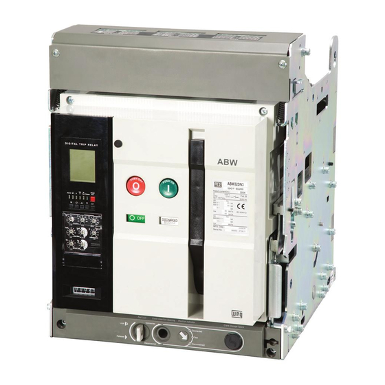
1.4 FRONT VIEW Fixed Withdrawable 1 - On button 2 - Off button 3 - Extinction chamber 4 - Identification plate 5 - Indicator of status of springs 6 - Indicator of status of circuit breaker 7 - Protection unit... -
Page 14: Codification
1.5 CODIFICATION ABW 16 DN 3 - 16 AZ1 F - A 0 2 2 0 Maximum current Accessories No accessories 800 A ON/OFF button lock 1,600 A Key lock 2,000 A Key interlock 2,500 A Phase sequence Mechanical interlock for 2 circuit... -
Page 15: Technical Data
1.6 TECHNICAL DATA Circuit breaker ABW08 ABW16 ABW20 ABW25 ABW32 ABW40 ABW50 ABW63 Standard IEC 60947-2 Maximum rated current (40 °C) - In max. (A) 1,600 2,000 2,500 3,200 4,000 5,000 6,300 Current setting (0.4 ~1.0) x In max... -
Page 16: Dimensions
1.7 DIMENSIONS Front View Horizontal Rear Terminal - Side View Insulation barrier Operating panel center 32.5 Vertical Rear Terminal - Side View Horizontal Rear Terminal - Top View (Insulation (Insulation barrier) barrier) 4 - Ø14 Assembly hole 32.5 32.5... - Page 17 Front View Horizontal Rear Terminal - Side View Disconnected & Test Zero arc space Connected Insulation barrier 2-M12 Tap CMB-U/F 38.5 4 - Ø13 Mounting hole Vertical Rear Terminal - Side View Horizontal Rear Terminal - Top View Disconnected & Test Disconnected &...
- Page 18 Front View Horizontal Rear Terminal - Side View Insulation barrier Operating panel center 32.5 Vertical Rear Terminal - Side View Horizontal Rear Terminal - Top View (Insulation (Insulation barrier) barrier) 4 - Ø14 Mounting hole 32.5 32.5 Vertical Rear Terminal - Top View Rear Terminal Dimensions 3 - Ø13...
- Page 19 Horizontal Rear Terminal - Side View Front View Disconnected & Test Connected Zero arc space Insulation barrier 2-M12 Tap CMB-U/F 38.5 6 - Ø13 Mounting hole Vertical Rear Terminal - Side View Horizontal Rear Terminal - Top View Disconnected & Test Disconnected &...
- Page 20 Front View Horizontal Rear Terminal - Side View Insulation barrier Operating panel center 67.5 Vertical Rear Terminal - Side View Horizontal Rear Terminal - Top View (Insulation (Insulation barrier) barrier) 4 - Ø14 Mounting hole 67.5 67.5 Rear Terminal Dimensions Vertical Rear Terminal - Side View 5 - Ø13...
- Page 21 Front View Horizontal Rear Terminal - Side View Disconnected & Test Zero arc space Connected 147.5 Operating panel center Insulation barrier 2-M12 Tap CMB-U/F 63.5 6 - Ø13 Mounting hole Vertical Rear Terminal - Side View Horizontal Rear Terminal - Top View Disconnected &...
- Page 22 Front View Horizontal Rear Terminal - Side View Insulation barrier Operating panel center 67.5 Vertical Rear Terminal - Side View Horizontal Rear Terminal - Top View (Insulation (Insulation barrier) barrier) 4 - Ø14 Mounting hole 67.5 67.5 Vertical Rear Terminal - Top View...
- Page 23 Front View Horizontal Rear Terminal - Side View Disconnected & Test Zero arc space Connected 186.5 Operating panel center Insulation barrier 2-M12 Tap CMB-U/F 63.5 6 - Ø13 Mounting hole Vertical Rear Terminal - Side View Horizontal Rear Terminal - Top View Disconnected &...
- Page 24 ABW08...32 10 - Ø9 315 (Panel cutout) Lower part of the withdrawable rack ABW40...63 10 - Ø9 315 (Panel cutout) Lower part of the withdrawable rack Figure 1.15: Panel Cutout - Fixed Version 24 | ABW - Air Circuit Breaker...
- Page 25 ABW08...16 Door frame 10 - Ø5 315 (Panel cutout) Lower part of the withdrawable rack Lower part of the withdrawable rack ABW20...32 Door frame 10 - Ø5 315 (Panel cutout) Lower part of the withdrawable rack Lower part of the withdrawable rack ABW40...50...
-
Page 26: Receipt Inspection
If there is any sign of damage or flaws caused by the transportation, inform the carrier and WEG directly. Also check that the information appearing on the product identification labels matches the item acquired. -
Page 27: Handling/Movement
1.10 HANDLING/MOVEMENT The circuit breakers can be easily moved by means of suspension cranes. Fork lifts can also be used. Pay attention to the weights of the circuit breakers and follow the recommendations of the figures below. Figure 1.18: Handling/Movement Other important recommendations „... -
Page 28: Installation
2 INSTALLATION 2.1 FIXED CIRCUIT BREAKER „ Fasten the circuit breaker by the side supports - (4x) M12 (4x) M12 Mounting 40-50 Nm bolt Figure 2.1: Fixed circuit breaker 2.2 DRAW -OUT CIRCUIT BREAKER „ Fasten the extraction car from inside - (4x, 6x, 8x) M12;... -
Page 29: Additional Precautions
2.3 ADDITIONAL PRECAUTIONS „ Do not lay the circuit breaker on its side; „ Install it on a flat surface; „ When installed on profiles, they must be lengthways to the circuit breaker. Lengthways rails Figure 2.3: Additional precautions 2.4 DO NOT LAY THE CIRCUIT BREAKER IN ITS SIDE... -
Page 30: Operation
3 OPERATION 3.1 MANUAL OPERATION CAUTION! Before operating a circuit breaker equipped with an subvoltage coil, the control circuit must be supplied. 3.1.1 Manual loading of the springs „ Maneuver the loading rod 7~8 times; „ At the end of the loading, the load indicator of the springs indicates “CHARGED”. -
Page 31: Electrical Operation
3.2 ELECTRICAL OPERATION The operation of the circuit breaker by electrical control is executed by means of the motorized drive and by the closing and opening coils, accessories installed internally in the circuit breaker. The motorized drive loads the springs of the operation mechanism automatically, whenever the circuit breaker is turned off, an operation which ends after approximately 5s. - Page 32 5. Maintaining the OFF button 6. Press the position pressed, insert the extraction lock. rod in the hole located in the lower part of the circuit breaker. 7. Turn the extraction rod a few times in a clockwise direction, until the circuit breaker reaches the TEST position.
-
Page 33: Extraction
3.3.2 Extraction 1. Maintaining the OFF button 2. Press the position lock. pressed, insert the extraction rod in the hole located in the lower part of the circuit breaker. 3. Turn the extraction rod a few times in a counterclockwise direction, until the circuit breaker reaches the TEST position. -
Page 34: Protection Units
4 PROTECTION UNITS 4.1 ADJUSTMENT SELECTORS N and A type units P and S type units Figure 4.1: Adjustment Selectors. Selector Function Short Adjustment range Nominal current (0.5 - 0.6 - 0.7 - 0.8 - 0.9 - 1.0) x In (0.8 - 0.83 - 0.85 - 0.88 - 0.89 - 0.9 - 0.93 -... -
Page 35: Adjustment Selectors
4.2 ADJUSTMENT SELECTORS N type units A, P and S type units Figure 4.2: Adjustment Selectors Function Indication Alarm It indicates possibility of overload (it goes on in 90% of the adjusted current and flashes above 105%) Battery / Self-test... -
Page 36: Protection Functions
Connector TTL TX (OCR side) CT - Ir ZSI OUT (+) RS485 (+) Power CT (-), Current signal - Ir ZSI OUT (-) DO relay #1 TTL RX (OCR side) CT - Is ZSI IN (+) RS485 (-) Power CT (+),... -
Page 37: Type A Units
4.4.2 Type A units Long delay Iu = In x ... Current of adjustment Ir = Iu x ... 0.80 0.83 0.85 0.88 0.93 0.95 0.98 tr @ 1.5xIr 12.5 Time of tr @ 6xIr adjustment tr @ 7.2xIr 0.34... -
Page 38: P And S Type Units
4.4.3 P and S type units Long delay Ir = In x ... Current of adjustment tr @ 1.5xIr 12.5 tr @ 6xIr Time of adjustment tr @ 7.2xIr 0.34 0.69 1.38 13.8 Precision: ± 15% ou < 100ms Short delay Isd = Ir x ... -
Page 39: Features Of Operation
4.5 FEATURES OF OPERATION 4.5.1 Long delay protection (L) Protection against overload, with feature of current inverse time. Figure 4.3: Long delay protection (L). 1. Current Ir a) Adjustment of range in N and A type units: (0.4~1.0) xIn - Iu: (0.5-0.6-0.7-0.8-0.9-1.0) xIn... -
Page 40: Instantaneous Protection (I)
4.5.3 Instantaneous protection (I) Protection against short-circuit (instantaneous performance). Figure 4.5: Instantaneous protection (I). 1. Current Ii - Adjustment of range: (2-3-4-6-8-10-12-15-Off) xIn 2. The unit performs as per the greatest current between the phases R, S, T and the neutral N. -
Page 41: Leakage Current To Ground Protection (G) - Optional
4.5.5 Leakage current to ground protection (G) - optional Protection against leakage current to ground, with feature of inverse time or defined time (optional for the A,P and S type protection units). Figure 4.7: Leakage current to ground protection (G) - optional. -
Page 42: Features And Instalation Instructions
Alarm time Accuracy Trip time Table 5.1: 5.2 DIMENSIONS: 5.2.1 Toroidal CT WEG (30/5 A ratio) Figure 5.1: Toroidal CT WEG (30/5 A ratio). 2 models available: Model ZCT-120 ZCR-200 5.3 EXTERNAL CT INSTALATION Toroidal CT must be connected on buses/conductors of breaker supply. Two secundary signal conductores of external CT must be connected on E1 and E2 protection unit terminals, a conductor in each terminal. -
Page 43: Rogramming Menus
5.4 ROGRAMMING MENUS CAUTION! „ The navigation between the different menus can be executed through the Menu and Esc keys. „ Use the keys to navigate between the submenus. „ If no key is pressed for 30s, the screen returns to the start menu (current measurement). -
Page 44: Keys
5.4.3 Keys Figure 5.5: Keys CAUTION! „ The type A unit has 6 keys; „ The LCD display lights up for 30s when a key is pressed; „ After 30s inactive, the display returns to the Measurement screen; „ When the unit is de-energized, upon pressing the key ESC/RESET the BATT LED goes on, indicating the battery charge;... -
Page 45: Protection Functions
5.4.5 Protection functions Menu Content Upon pressing the key M from the measurement screen, the screens of checking Current parameters of protection functions are accessed. The long delay protection is the first to appear on the screen. The other functions... -
Page 46: Other Functions
5.4.6 Other Functions Menu Tecla Contenido Upon pressing (2x) the key M from the measurement screen, the screen of configuration of communication in network (address) is accessed. The address can be selected 1 thru 247. Address Upon pressing the key Enter, the adjustment is saved, or, upon pressing the key Esc/ Reset, one returns to the measurement screen without saving it. -
Page 47: Communication In Network, Clock And List Of Events
5.4.7 Communication in network, clock and list of events Display Content Upon pressing the key Enter from the index of events, the information of the date (year/ month) of the occurrence is shown. 1. The bar charts indicate that it is the 7 event of the list. -
Page 48: Tripping Curves
6 TRIPPING CURVES 6.1 LONG DELAY PROTECTION (FUNCTION L) Figure 6.1: long Delay protection (Function l). 48 | ABW - Air Circuit Breaker... -
Page 49: Short Delay Protection (Function S)
6.2 SHORT DELAY PROTECTION (FUNCTION S) Figure 6.2: Short Delay protection (Function S). ABW - Air Circuit Breaker | 49... -
Page 50: Instantaneous (Function I) And Shortage Current To Ground (Function G) Protection
6.3 INSTANTANEOUS (FUNCTION I) AND SHORTAGE CURRENT TO GROUND (FUNCTION G) PROTECTION Figure 6.3: Instantaneous (Function I) and Shortage Current to ground (Function g) protection. 50 | ABW - Air Circuit Breaker... -
Page 51: Protection Against Defined Time Type Overcurrents (Idmtl)
6.4 PROTECTION AGAINST DEFINED TIME TYPE OVERCURRENTS (IDMTL) Figure 6.4: Protection against defined time type overcurrents (IDMTL) ABW - Air Circuit Breaker | 51... -
Page 52: Protection Against Defined Time Type Shortage Current To Ground (Idmtl)
6.5 PROTECTION AGAINST DEFINED TIME TYPE SHORTAGE CURRENT TO GROUND (IDMTL) Figure 6.5: Protection against defined time type shortage current to ground (IDMTL) 52 | ABW - Air Circuit Breaker... -
Page 53: Inspection And Maintenance Cycles
7 INSPECTION AND MAINTENANCE CYCLES Service conditions Environment Typical examples Inspection cycle Estimated useful life Electrical rooms, with air Clean and dry air filters and air-conditioning Sheltered installation Normal Every 2 years Approx. 10 years Distribution panels or with little dust, without... - Page 54 2. Defect in undervoltage coil. 2. Change undervoltage coil. The circuit breaker does not open by manual 1. Defect in operation mechanism. 1. Contact WEG. command. 1. Eliminate short-circuit. Check state of circuit 1. The circuit breaker closed under short-circuit.
- Page 55 9 ABW WIRING DIAGRAM This diagram considers the ABW in the inserted position, in the open position (OFF) and motor loaded. In the withdrawable version (with truck), the truck release latch must be in the regular (released) position. Accessory code description:...
- Page 57 Manual del Usuario Série: ABW Interruptor Abierto Idioma: Español...
- Page 59 Índice Índice 1 INTRODUCCIÓN 1.1 CONSIDERACIONES SOBRE SEGURIDAD ..................62 1.1.1 Orientaciones preliminares .......................62 1.1.2 Profesionales calificados ......................62 1.1.3 Mensajes de alerta ........................62 1.2 CONDICIONES DE SERVICIO ......................64 1.2.1 Temperatura ambiente ......................64 1.2.2 Altitud de instalación ........................64 1.2.3 Humedad relativa ........................65 1.2.4 Presencia de gases ........................65 1.2.5 Instalación - distancias mínimas de instalación y aislamiento de tensión ......65 1.3 ESTRUTURA ............................66...
- Page 60 5 CARACTERÍSTICAS E INSTRUCIONES DE INSTALACIÓN 5.1 AJUSTE DE CORRIENTE DE FUGA A TIERRA: ................96 5.2 DIMENSIONES: ...........................96 5.2.1 TC toroidal WEG (relación 30/5 A) ....................96 5.3 INSTALACIÓN DEL TC EXTERNO .....................96 5.4 MENÚS DE PROGRAMACIÓN ......................97 5.4.1 Menús ............................97 5.4.2 Pantalla de LCD ........................97...
-
Page 62: Introducción
WEG se reserva el derecho de realizar cualquier alteración en las especificaciones aquí contenidas o de promover mejoras a cualquier instante, sin previo aviso. Habiendo conflicto entre las informaciones contenidas en esta publicación y el contenido de diseños, material suplementario, o ambos, éstos últimos deben prevalecer. - Page 63 Efectúe una inspección visual inmediatamente después del recibimiento del interruptor automático, y aún antes de retirarlo del pallet. En caso que haya cualquier evidencia de daños o imperfecciones ocasionadas por el transporte, informe directamente a la transportadora y la WEG. „ Transporte Mantenga el interruptor automático sujetado al pallet y transporte elconjunto con una carretilla o montacargas.
-
Page 64: Condiciones De Servicio
1.2 CONDICIONES DE SERVICIO 1.2.1 Temperatura ambiente „ Operación: -5...40 ºC, con promedio en 24 horas de hasta 35 ºC. Para aplicación de los interruptores automáticos ABW en ambientes con temperatura superior a 40 °C, considere los valores máximos de corriente... -
Page 65: Humedad Relativa
1.2.3 Humedad relativa ≤ 85% @ 40 ºC. ≤ 90% @ 20 ºC. 1.2.4 Presencia de gases S ≤ 0,01 ppm; SO ≤ 0,01 ppm. 1.2.5 Instalación - distancias mínimas de instalación y aislamiento de tensión Figura 1.1: Tipo Fijo1 Extraíble... -
Page 66: Estrutura
1.3 ESTRUTURA Bloque de conexiones de comando Terminales de conexión Terminales de conexión Bloque de contactos auxiliares Bobinas Unidad de protecctión Tapa frontal Mecanismo de operación Varilla de carga Tcs internos Resortes de abertura Resortes de cierre Sistema de inserción/extracción Terminales inferiores Cámara de extinción... -
Page 67: Vista Frontal
1.4 VISTA FRONTAL Fijo Extraíble 1 - Botón de encendido 2 - Botón de apagado 3 - Cámara de extinción 4 - Placa de identificación 5 - Indicador de estado de los resortes 6 - Indicador de estado del interruptor automático... -
Page 68: Codificación
1.5 CODIFICACIÓN ABW 16 DN 3 - 16 AZ1 F - A 0 2 2 0 Accesorios Corriente máxima Sin accesorios 800 A Bloqueo de botones L/D 1.600 A Bloqueo por llave 2.000 A Enclavamiento por llave 2.500 A Secuencia de fases Enclavamiento mecánico para 2... -
Page 69: Datos Técnicos
1.6 DATOS TÉCNICOS Interruptor ABW08 ABW16 ABW20 ABW25 ABW32 ABW40 ABW50 ABW63 Normativa IEC 60947-2 Corriente nominal máxima (40 °C) - In máx. (A) 1,600 2,000 2,500 3,200 4,000 5,000 6,300 Ajuste de corriente (0.4 ~1.0) x In máx Tensión nominal de operación - Ue (V) -
Page 70: Dimensiones
1.7 DIMENSIONES Vista Frontal Terminal Trasero Horizontal - Vista Lateral Barrera de aislamiento Centro del tablero de operación 32.5 Terminal Trasero Vertical - Vista Lateral Terminal Trasero Horizontal: Vista Superior (Insulation (Barrera de aislamiento) barrier) 4 - Ø14 Orificio de montaje 32.5... - Page 71 Vista Frontal Terminal Trasero Horizontal - Vista Lateral Desconectado & Prueba Cámara de extinción cero arco Conectado Barrera de aislamiento 2-M12 Tap CMB-U/F 38.5 4 - Ø13 Orificio de montaje Terminal Trasero Vertical - Vista Lateral Terminal Trasero Horizontal: Vista Superior Disconnected &...
- Page 72 Vista Frontal Terminal Trasero Horizontal - Vista Lateral Barrera de aislamiento Centro del tablero de operación 32.5 Terminal Trasero Vertical - Vista Lateral Terminal Trasero Horizontal: Vista Superior (Insulation (Barrera de barrier) aislamiento) 4 - Ø14 Orificio de montaje 32.5...
- Page 73 Terminal Trasero Horizontal - Vista Lateral Vista Frontal Desconectado & Prueba Conectado Cámara de extinción cero arco Barrera de aislamiento 2-M12 Tap CMB-U/F 38.5 6 - Ø13 Orificio de montaje Terminal Trasero Vertical - Vista Lateral Terminal Trasero Horizontal: Vista Superior Desconectado &...
- Page 74 Vista Frontal Terminal Trasero Horizontal - Vista Lateral Barrera de aislamiento Centro del tablero de operación 67.5 Terminal Trasero Vertical - Vista Lateral Terminal Trasero Horizontal: Vista Superior (Insulation (Barrera de barrier) aislamiento) 4 - Ø14 Orificio de montaje 67.5...
- Page 75 Vista Frontal Terminal Trasero Horizontal - Vista Lateral Desconectado & Prueba Cámara de extinción cero arco Conectado 147.5 Centro del tablero de operación Barrera de aislamiento 2-M12 Tap CMB-U/F 63.5 6 - Ø13 Orificio de montaje Terminal Trasero Vertical - Vista Lateral Terminal Trasero Horizontal: Vista Superior Disconnected &...
- Page 76 Vista Frontal Terminal Trasero Horizontal - Vista Lateral Barrera de aislamiento Centro del tablero de operación 67.5 Terminal Trasero Vertical - Vista Lateral Terminal Trasero Horizontal: Vista Superior (Insulation (Barrera de barrier) aislamiento) 4 - Ø14 Orificio de montaje 67.5...
- Page 77 Vista Frontal Terminal Trasero Horizontal - Vista Lateral Desconectado & Prueba Cámara de extinción cero arco Conectado 186.5 Centro del tablero de operación Barrera de aislamiento 2-M12 Tap CMB-U/F 63.5 6 - Ø13 Orificio de montaje Terminal Trasero Vertical - Vista Lateral Terminal Trasero Horizontal: Vista Superior Desconectado &...
- Page 78 ABW08...32 10 - Ø9 315 (Ranura tablero) Parte inferior del carro de extracción ABW40...63 10 - Ø9 315 (Ranura tablero) Parte inferior del carro de extracción Figura 1.15: Ranura Tablero - Versión Fija 78 | ABW Interruptor Abierto...
- Page 79 ABW08...16 Marco puerta 10 - Ø5 315 (Ranura tablero) Parte inferior del carro de extracción Parte inferior del carro de extracción ABW20...32 Marco puerta 10 - Ø5 315 (Ranura tablero) Parte inferior del carro de extracción Parte inferior del carro de extracción ABW40...50...
-
Page 80: Inspección De Recibimiento
Al desembalarlo, efectúe inspección visual del interruptor automático, aún antes de retirarlo del pallet. En caso que haya alguna evidencia de daños o imperfecciones ocasionadas por el transporte, informe directamente a la transportadora y a WEG. Verifique también si las informaciones que constan en las etiquetas de identificación del producto corresponden al ítem adquirido. -
Page 81: Manipulación/Movimiento
1.10 MANIPULACIÓN/MOVIMIENTO Los interruptores automáticos pueden ser fácilmente movidos por medio de polipastos o grúas de suspensión. También pueden ser utilizados montacargas. Observe la relación de pesos de los interruptores automáticos y siga las recomendaciones de las figuras de abajo. -
Page 82: Instalación
2 INSTALACIÓN 2.1 INTERRUPTOR AUTOMÁTICO FIJO „ Fije el interruptor automático a través de los soportes laterales - (4x) M12 (4x) M12 Mounting 40-50 Nm bolt Figura 2.1: Interruptor automático fijo. 2.2 INTERRUPTOR AUTOMÁTICO EXTRAÍBLE „ Fije el carro de extracción por dentro - (4x, 6x, 8x) M12;... -
Page 83: Precauciones Adicionales
2.3 PRECAUCIONES ADICIONALES „ No apoye el interruptor automático sobre su lateral; „ Instálelo sobre superficie plana; „ Cuando instalado sobre perfiles, éstos deben ser longitudinales al interruptor automático Guías longitudinales Figura 2.3: Precauciones adicionales. 2.4 INSTALACIÓN DE LAS DIVISORIAS AISLANTES „... -
Page 84: Operación
3 OPERACIÓN 3.1 OPERACIÓN MANUAL ¡CUIDADO! Antes de operar un interruptor automático equipado con bobina de subtensión, se debe alimentar el circuito de comando. 3.1.1 Carga manual de los resortes „ Maniobrar la varilla de carga por 7~8 veces;... -
Page 85: Operación Eléctrica
3.2 OPERACIÓN ELÉCTRICA La operación del interruptor automático por comando eléctrico es hecha por medio del accionamiento motorizado y por las bobinas de cierre y de abertura, accesorios instalados internamente en el interruptor automático. El accionamiento motorizado carga los resortes del mecanismo de operación automáticamente, siempre que el interruptor automático sea apagado, operación que finaliza después de aproximadamente 5 segundos. - Page 86 5. Manteniendo el botón de 6. Presione la traba de apagado presionado, inserte la posición. varilla de extracción en el orifício localizado en la parte inferior del interruptor automático. 7. Gi r e l a vari l l a de extracci ó n al g unas vuel t as haci a l a derecha, hasta que el i n terruptor automáti c o...
-
Page 87: Extracción
3.3.2 Extracción 1. Manteniendo el botón de 2. Presione la traba de posición. apagado presionado, inserte la varilla de extracción en el orificio localizado en la parte inferior del interruptor automático. 3. Gi r e l a vari l l a de extracci ó n al g unas vuel t as haci a l a derecha, hasta que el i n terruptor automáti c o... -
Page 88: Unidades De Protección
4 UNIDADES DE PROTECCIÓN 4.1 SELECTORES DE AJUSTE Unidades tipo N y A Unidades tipo P y S Figura 4.1: Selectores de ajuste. Selector Función Sigla Rango de ajuste Corriente nominal (0.5 - 0.6 - 0.7 - 0.8 - 0.9 - 1.0) x In (0.8 - 0.83 - 0.85 - 0.88 - 0.89 - 0.9 - 0.93 -... -
Page 89: Selectores De Ajuste
4.2 SELECTORES DE AJUSTE Unidades tipo N Unidades tipo A, P Y S Figura 4.2: Selectores de ajuste Función Indicación Indica posibilidad de sobrecarga Alarma (se enciende en 90% de lacorriente ajustada y destella arriba de 105%) Batería/Autoprueba Autoprueba de la unidad de protección y carga de la batería... -
Page 90: Funciones De Protección
Connector TTL TX (OCR side) CT - Ir ZSI OUT (+) RS485 (+) Power CT (-), Current signal - Ir ZSI OUT (-) DO relay #1 TTL RX (OCR side) CT - Is ZSI IN (+) RS485 (-) Power CT (+),... -
Page 91: Unidades Tipo A
4.4.2 Unidades tipo A Longo retardo (L) Iu = In x ... Ajuste de corriente Ir = Iu x ... 0.80 0.83 0.85 0.88 0.93 0.95 0.98 tr @ 1.5xIr 12.5 Ajuste de tr @ 6xIr tiempo (s) tr @ 7.2xIr 0.34... -
Page 92: Unidades Tipo P Y S
4.4.3 Unidades tipo P y S Longo retardo (L) Ir = In x ... Ajuste de corriente tr @ 1.5xIr 12.5 tr @ 6xIr Ajuste de tr @ 7.2xIr 0.34 0.69 1.38 13.8 tiempo (s) Precisión: ± 15% ou < 100ms Curto retardo (S) Isd = Ir x ... -
Page 93: Subfrecuencia
4.5 SUBFRECUENCIA 4.5.1 Protección de largo retardo (L) Protección contra sobrecarga, con característica de tiempo inverso a la. Figura 4.3: Protección de largo retardo (L). 1. Corriente Ir a) Rango de ajuste en las unidades de los tipos N: y A: (0,4~1,0) xIn - Iu: (0.5-0.6-0.7-0.8-0.9-1.0) xIn... -
Page 94: Instantaneous Protection (I)
4.5.3 Instantaneous protection (I) Protección contra cortocircuito (actuación instantánea). Figura 4.5: Protección instantánea (I). 1. Corriente Ii - Rango de ajuste: (2-3-4-6-8-10-12-15-Off) xIn 2. La unidad actúa conforme la mayor corriente entre las fases R, S, T y el neutro N. -
Page 95: Protección De Fuga A Descarga A Tierra (G) - Opcional
4.5.5 Protección de fuga a descarga a tierra (g) - opcional Protección contra fuga a descarga a tierra, con característica de tiempo inverso o de tiempo definido (opcional para las unidades de protección de los tipos A, P y S). -
Page 96: Características E Instruciones De Instalación
Tiempo de Precisión desconexión Tabla 5.1: 5.2 DIMENSIONES: 5.2.1 TC toroidal WEG (relación 30/5 A) Figura 5.1: TC toroidal WEG (relación 30/5 A). Disponibles en 2 referencias: Referencia ZCT-120 ZCR-200 5.3 INSTALACIÓN DEL TC EXTERNO El Transformador de Corriente (TC) toroidal debe ser conectado en los conductores/ barras de alimentación del interruptor. -
Page 97: Menús De Programación
5.4 MENÚS DE PROGRAMACIÓN ¡CUIDADO! „ La navegación entre los diferentes menús puede ser hecha a través de las teclas Menu y Esc. „ Utilice las teclas para navegar entre los submenús. „ En el caso que no se presione ninguna tecla por 30s, la pantalla volverá al menú inicial (medición de corriente). -
Page 98: Teclas
5.4.3 Teclas Figura 5.5: Teclas ¡CUIDADO! „ La unidad tipo A posee 6 teclas; „ El display LCD se ilumina por 30s cuando una tecla es presionada; „ Después de 30s de inactividad, el display vuelve a la pantalla de Medición „... -
Page 99: Funciones De Protección
5.4.5 Funciones de protección Menu Tecla Contenido Al presionarse la tecla M a partir de la pantalla de medición, se accede a las Corriente pantallas de verificación de parámetros de las funciones de protección. La protección de largo retardo es la primera a surgir en la pantalla. Las otras funciones pueden ser accedidas a través de las teclas... -
Page 100: Comunicación En Red, Reloj Y Lista De Eventos
5.4.6 Comunicación en red, reloj y lista de eventos Menu Tecla Contenido Al presionarse (2x) la tecla M a partir de la pantalla de medición, se accede a la pantalla de configuración de la comunicación en red (dirección). La dirección puede ser seleccionada de 1 a 247. -
Page 101: Comunicación En Red, Reloj Y Lista De Eventos
5.4.7 Comunicación en red, reloj y lista de eventos Display Tecla Contenido Al presionarse la tecla Enter a partir del índice de eventos, las informaciones de la fecha (año/mes) del evento son mostradas. 1. Las barras gráficas indican que este es el 7º evento de la lista. -
Page 102: Curvas De Disparo
6 CURVAS DE DISPARO 6.1 PROTECCIÓN DE LARGO RETARDO (FUNCIÓN L) Figura 6.1: proteción de largo retardo (Función l) 102 | ABW Interruptor Abierto... -
Page 103: Protección De Corto Retardo (Función S)
6.2 PROTECCIÓN DE CORTO RETARDO (FUNCIÓN S) Figura 6.2: protección de corto retardo (Función S) ABW Interruptor Abierto | 103... -
Page 104: Protección Instantánea (Función I) E De Falta De Descarga A Tierra
6.3 PROTECCIÓN INSTANTÁNEA (FUNCIÓN I) E DE FALTA DE DESCARGA A TIERRA (FUNCIÓN (G) Figura 6.3: proteccoón ansantánea (Función I) e de falta de descarga a tierra (Función (g). 104 | ABW Interruptor Abierto... -
Page 105: Protección Contra Sobrecorrientes Del Tipo Tiempo Definido (Idmtl)
6.4 PROTECCIÓN CONTRA SOBRECORRIENTES DEL TIPO TIEMPO DEFINIDO (IDMTL) Figura 6.4: protección contra sobrecorrientes del tipo tiempo definido (IDMTL) ABW Interruptor Abierto | 105... -
Page 106: Protección Contra Falta De Descarga A Tierra Del Tipo Tiempo Definido (Idmtl)
6.5 PROTECCIÓN CONTRA FALTA DE DESCARGA A TIERRA DEL TIPO TIEMPO DEFINIDO (IDMTL) Figura 6.5: protección contra falta de descarga a tierra del tipo tiempo definido (IDMTL) 106 | ABW Interruptor Abierto... -
Page 107: Ciclos De Inspección Y Mantenimiento
7 CICLOS DE INSPECCIÓN Y MANTENIMIENTO Condiciones Ambiente Ejemplos típicos Ciclo de inspección Vida útil estimada de servicio Salas eléctricas, con Aire limpio y seco filtros de aire y aire acondicionado Normales A cada 2 años Aprox. 10 años Paneles de distribución o... - Page 108 2. Defecto en la bobina de subtensión. 2. Cambiar bobina de subtensión. eléctrico. El interruptor utomático no abre por comando 1. Defecto en el mecanismo de peración. 1. Contactar a WEG. manual. 1. El interruptor automático cerró bajo 1. Eliminar el cortocircuito. Verificar el estado cortocircuito.
- Page 109 9 DIAGRAMA DE CONEXIÓN ABW Este diagrama considera el ABW en la posición conectada, en la posición abierta (apagado) y el motor cargado. En la versión extraíble (con carro de extracción), el pestillo de liberación del carro debe estar en la posición normal (liberado).
- Page 111 Manual do Usuário Série: ABW Disjuntor Aberto Idioma: Português...
- Page 113 Sumário Sumário 1 INTRODUÇÃO 1.1 CONSIDERAÇÕES SOBRE SEGURANÇA ..................116 1.1.1 Orientações preliminares ......................116 1.1.2 Profissionais qualificados .......................116 1.1.3 Mensagens de alerta .......................116 1.2 CONDIÇÕES DE SERVIÇO ......................118 1.2.1 Temperatura ambiente ......................118 1.2.2 Altitude de instalação ......................118 1.2.3 Umidade relativa ........................119 1.2.4 Presença de gases ........................119 1.2.5 Instalação - distâncias mínimas de instalação e isolação de tensão ........119 1.3 ESTRUTURA .............................120...
- Page 114 Sumário 5 CARACTERÍSTICAS E INSTRUÇÕES DE INSTALAÇÃO 5.1 AJUSTE DE FUGA:..........................150 5.2 DIMENSIONAIS: ..........................150 5.2.1 TC toroidal WEG (relação 30/5 A) ...................150 5.3 INSTALAÇÃO DO TC EXTERNO ......................150 5.4 MENUS DE PROGRAMAÇÃO ......................151 5.4.1 Menus ............................151 5.4.2 Tela de LCD ..........................151 5.4.3 Teclas ............................152...
-
Page 116: Introdução
A WEG se reserva o direito de promover quaisquer alterações nas especificações aqui contidas ou de promover melhorias a qualquer instante, sem prévio aviso. Havendo conflito entre as informações contidas nesta publicação e o conteúdo de desenhos, material suplementar, ou ambos, estes últimos devem prevalecer. - Page 117 Efetuar inspeção visual imediatamente após recebimento do disjuntor, e antes mesmo de removê-lo do pallet. Caso haja qualquer evidência de danos ou imperfeições ocasionadas pelo transporte, informar diretamente a transportadora e a WEG. „ Transporte Mantenha o disjuntor preso ao pallet e transporte o conjunto com um carrinho ou empilhadeira.
-
Page 118: Condições De Serviço
1.2 CONDIÇÕES DE SERVIÇO 1.2.1 Temperatura ambiente „ Operação: -5...40 °C, com média em 24h de até 35 °C. Para aplicação dos disjuntores ABW em ambientes com temperatura acima de 40 °C, considerar os valores máximos de corrente nominal apresentados na... -
Page 119: Umidade Relativa
1.2.3 Umidade relativa ≤ 85% @ 40 ºC. ≤ 90% @ 20 ºC. 1.2.4 Presença de gases S ≤ 0,01 ppm; SO ≤ 0,01 ppm. 1.2.5 Instalação - distâncias mínimas de instalação e isolação de tensão Figura 1.1: Tipo Fixo Extraível... -
Page 120: Estrutura
1.3 ESTRUTURA Bloco de conexões de comando Terminais de conexão Terminais de ligação Bloco de contatos auxiliares Bobinas Unidade de proteção Tampa frontal Mecanismo de operação Haste de carregamento TCs internos Molas de abertura Molas de fechamento Sistema de inserção/extração Terminais inferiores Câmara de extinção... -
Page 121: Configurações De Terminais
Disjuntor fixo Disjuntor extraível 1 - Botão liga 2 - Botão desliga 3 - Câmara de extinção 4 - Placa de identificação 5 - Indicador de estado das molas 6 - Indicador de estado do disjuntor 7 - Unidade de proteção... -
Page 122: Codificação
1.5 CODIFICAÇÃO ABW 16 DN 3 - 16 AZ1 F - A 0 2 2 0 Acessórios Corrente máxima Sem acessórios 800 A Bloqueio de botões L/D 1.600 A Bloqueio por chave 2.000 A Intertravamento por chave 2.500 A Sequência de fases... -
Page 123: Dados Técnicos
1.6 DADOS TÉCNICOS Disjuntor ABW08 ABW16 ABW20 ABW25 ABW32 ABW40 ABW50 ABW63 Norma IEC 60947-2 Corrente nominal máxima (40 °C) - In 1,600 2,000 2,500 3,200 4,000 5,000 6,300 Ajuste de corrente (0.4 ~1.0) x In max Tensão nominal de operação - Ue (V) Tensão nominal de isolação - Ui (V) -
Page 124: Dimensões
1.7 DIMENSÕES Vista Frontal Terminal Traseiro Horizontal - Vista Lateral Barreira de isolação Centro do painel de operação 32.5 Terminal Traseiro Vertical - Vista Lateral Terminal Traseiro Horizontal - Vista Superior (Insulation (Barreira de isolação) barrier) 4 - Ø14... - Page 125 Vista Frontal Terminal Traseiro Horizontal - Vista Lateral Desconectado & Teste Câmara de extinção zero arco Conectado Barreira de isolação 2-M12 Tap CMB-U/F 38.5 4 - Ø13 Furo de montagem Terminal Traseiro Vertical - Vista Lateral Terminal Traseiro Horizontal - Vista Superior Disconnected &...
- Page 126 Vista Frontal Terminal Traseiro Horizontal - Vista Lateral Barreira de isolação Centro do painel de operação 32.5 Terminal Traseiro Vertical - Vista Lateral Terminal Traseiro Horizontal - Vista Superior (Insulation (Barreira de barrier) isolação) 4 - Ø14 Furo de montagem 32.5...
- Page 127 Terminal Traseiro Horizontal - Vista Lateral Vista Frontal Desconectado & Teste Conectado Câmara de extinção zero arco Barreira de isolação 2-M12 Tap CMB-U/F 38.5 6 - Ø13 Furo de montagem Terminal Traseiro Vertical - Vista Lateral Terminal Traseiro Horizontal - Vista Superior Desconectado &...
- Page 128 Vista Frontal Terminal Traseiro Horizontal - Vista Lateral Barreira de isolação Centro del tablero de operación 67.5 Terminal Traseiro Vertical - Vista Lateral Terminal Traseiro Horizontal - Vista Superior (Insulation (Barreira de barrier) isolação) 4 - Ø14 Furo de montagem 67.5...
- Page 129 Vista Frontal Terminal Traseiro Horizontal - Vista Lateral Desconectado & Teste Câmara de extinção zero arco Conectado 147.5 Centro do painel de operação Barreira de isolação 2-M12 Tap CMB-U/F 63.5 6 - Ø13 Furo de montagem Terminal Traseiro Vertical - Vista Lateral Terminal Traseiro Horizontal - Vista Superior Disconnected &...
- Page 130 Vista Frontal Terminal Traseiro Horizontal - Vista Lateral Barreira de isolação Centro do painel de operação 67.5 Terminal Traseiro Vertical - Vista Lateral Terminal Traseiro Horizontal - Vista Superior (Insulation (Barreira de barrier) isolação) 4 - Ø14 Furo de montagem 67.5...
- Page 131 Vista Frontal Terminal Traseiro Horizontal - Vista Lateral Desconectado & Teste Câmara de extinção zero arco Conectado 186.5 Centro do painel de operação Barreira de isolação 2-M12 Tap CMB-U/F 63.5 6 - Ø13 Furo de montagem Terminal Traseiro Vertical - Vista Lateral Terminal Traseiro Horizontal - Vista Superior Desconectado &...
- Page 132 ABW08...32 10 - Ø9 315 (Rasgo painel) Parte inferior do carro de extração ABW40...63 10 - Ø9 315 (Rasgo painel) Parte inferior do carro de extração Figura 1.15: Rasgo Painel - Versão Fixa 132 | ABW Disjuntor Aberto...
- Page 133 ABW08...16 Moldura porta 10 - Ø5 315 (Rasgo painel) Parte inferior do carro de extração Parte inferior do carro de extração ABW20...32 Moldura porta 10 - Ø5 315 (Rasgo painel) Parte inferior do carro de extração Parte inferior do carro de extração ABW40...50...
-
Page 134: Inspeção De Recebimento
Caso haja qualquer evidência de danos ou imperfeições ocasionadas pelo transporte, informar diretamente a transportadora e a WEG. Verifique também se as informações constantes nas etiquetas de identificação do produto correspondem ao item adquirido. -
Page 135: Manuseio/Movimentação
1.10 MANUSEIO/MOVIMENTAÇÃO Os disjuntores podem ser facilmente movimentados por meio de guindastes de suspensão. Empilhadeiras também podem ser utilizadas. Atentar para os pesos dos disjuntores e seguir as recomendações das figuras abaixo Figura 1.18: Manuseio/Movimentação Outras recomendações importantes „ Quando estiver movimentando o disjuntor, faça-o lentamente, evitando impactos ao mesmo;... -
Page 136: Instalação
2 INSTALAÇÃO 2.1 DISJUNTORES FIXOS „ Fixar o disjuntor pelos suportes laterais - (4x) M12. (4x) M12 Mounting 40-50 Nm bolt Figura 2.1: Disjuntores Fixos. 2.2 DISJUNTORES EXTRAÍVEIS „ Fixar o carro de extração por dentro - (4x, 6x ou 8x) M12;... -
Page 137: Precauções Adicionais
2.3 PRECAUÇÕES ADICIONAIS „ Não deitar o disjuntor sobre sua lateral; „ Instalá-lo sobre superfície plana; „ Quando instalado sobre perfis, estes devem ser longitudinais ao disjuntor. Trilhos longitudinais Figura 2.3: Precauções adicionais. 2.4 INSTALAÇÃO DAS DIVISÓRIAS ISOLANTES „ Disjuntor fixo: encaixar pela face “A”. -
Page 138: Operação
3 OPERAÇÃO 3.1 OPERAÇÃO MANUAL CUIDADO! Antes de operar um disjuntor equipado com bobina de subtensão, deve-se alimentar o circuito de comando. 3.1.1 Carregamento manual das molas „ Manobrar a haste de carregamento por 7~8 vezes; „ Ao final do carregamento, o indicador de carga das molas indica “CHARGED”. -
Page 139: Operação Elétrica
3.2 OPERAÇÃO ELÉTRICA A operação do disjuntor por comando elétrico é feita por meio do acionamento motorizado e pelas bobinas de fechamento e de abertura, acessórios instalados internamente no disjuntor. O acionamento motorizado carrega as molas do mecanismo de operação automaticamente, sempre que o disjuntor é... - Page 140 5. Mantendo o botão desliga 6. Pressione a trava pressionado, inserir a haste de de posição. extração do orifício localizado na parte inferior do disjuntor. 7. Gi r e a haste de extração al g umas vol t as no senti d o horári o , até...
-
Page 141: Extração
3.3.2 Extração 1. Mantendo o botão desliga 2. Pressionar a trava de pressionado, inserir a haste de posição. extração no orifício localizado na parte inferior do disjuntor. 3. Gi r ar a haste de extração al g umas vol t as no senti d o anti - horári o , até... -
Page 142: Unidades De Proteção
4 UNIDADES DE PROTEÇÃO 4.1 SELETORES DE AJUSTE Unidades tipo N e A Unidades tipo P e S Figura 4.1: Seletores de ajuste. Seletor Função Sigla Faixa de ajuste Corrente nominal (0.5 - 0.6 - 0.7 - 0.8 - 0.9 - 1.0) x In (0.8 - 0.83 - 0.85 - 0.88 - 0.89 - 0.9 - 0.93 -... -
Page 143: Leds De Sinalização E Teclas De Navegação
4.2 LEDS DE SINALIZAÇÃO E TECLAS DE NAVEGAÇÃO Unidades tipo N Unidades tipo A, P Y S Figura 4.2: Leds de sinalização e teclas de navegação LEDs Quando inicialmente ligada, a unidade de proteção apresenta a tela abaixo no display, por aproximadamente 2 segundos: Função... -
Page 144: Funções De Proteção
Conector TTL TX (OCR side) CT - Ir ZSI OUT (+) RS485 (+) Power CT (-), Current signal - Ir ZSI OUT (-) DO relay #1 TTL RX (OCR side) CT - Is ZSI IN (+) RS485 (-) Power CT (+),... -
Page 145: Unidades Tipo A
4.4.2 Unidades tipo A Longo retardo (L) Iu = In x ... Ajuste de corriente Ir = Iu x ... 0.80 0.83 0.85 0.88 0.93 0.95 0.98 tr @ 1.5xIr 12.5 Ajuste de tr @ 6xIr tempo (s) tr @ 7.2xIr 0.34... -
Page 146: Unidades Tipo P E S
4.4.3 Unidades tipo P e S Longo retardo (L) Ir = In x ... Ajuste de corrente tr @ 1.5xIr 12.5 tr @ 6xIr Ajuste de tr @ 7.2xIr 0.34 0.69 1.38 13.8 tempo (s) Precisão: ± 15% ou < 100ms Curto retardo (S) Isd = Ir x ... -
Page 147: Características De Operação
4.5 CARACTERÍSTICAS DE OPERAÇÃO 4.5.1 Proteção de longo retardo (L) Proteção contra sobrecarga, com característica de tempo inverso à corrente. Figura 4.3: Proteção de longo retardo (L). 1. Corrente Ir a) Faixa de ajuste nas unidades dos tipos N e A: (0.4~1.0) xIn... -
Page 148: Proteção Instantânea (I)
4.5.3 Proteção instantânea (I) Proteção contra curto-circuito (atuação instantânea). Figura 4.5: Proteção instantânea (I). 1. Corrente Ii - Faixa de ajuste: (2-3-4-6-8-10-12-15-Off) xIn 2. A unidade atua conforme a maior corrente entre as fases R, S, T e o neutro N. -
Page 149: Proteção De Fuga-À-Terra (G) - Opcional
4.5.5 Proteção de fuga-à-terra (G) - opcional Proteção contra fuga-à-terra, opção de disparo (trip) ou alarme (opcional para as unidades de proteção dos tipos A, P e S). Figura 4.7: Proteção contra fuga-à-terra, opção de disparo (trip) ou alarme (opcional para as unidades de proteção dos tipos A, P e S. -
Page 150: Características E Instruções De Instalação
Desarme Precisão tempo Tabela 5.1: 5.2 DIMENSIONAIS: 5.2.1 TC toroidal WEG (relação 30/5 A) Figura 5.1: TC toroidal WEG (relação 30/5 A). Disponíveis em 2 modelos: Modelo ZCT-120 ZCR-200 5.3 INSTALAÇÃO DO TC EXTERNO O TC toroidal deve ser ligado nos condutores/barramentos de alimentação do disjuntor. Os dois condutores de sinal do secundário que saem do TC toroidal externo, devem ser ligados nos bornes E1 e E2 da Unidade de... -
Page 151: Menus De Programação
5.4 MENUS DE PROGRAMAÇÃO CUIDADO! „ A navegação entre os diferentes menus pode ser feita através das teclas Menu e Esc. „ Utilizar as teclas para navegar entre os submenus. „ Caso não se pressione nenhuma tecla por 30s, a tela volta ao menu inicial (medição de corrente). -
Page 152: Teclas
5.4.3 Teclas Figura 5.5: Teclas CUIDADO! „ A unidade tipo A possui 6 teclas; „ O display LCD se ilumina por 30s quando uma tecla é pressionada; „ Após 30s inativo, o display volta à tela inicial (medição de corrente);... -
Page 153: Funções De Proteção
5.4.5 Funções de proteção Menu Tecla Contenido Ao pressionar-se a tecla M a partir da tela de medição, acessa-se as telas de Corrente verificação de parâmetros das funções de proteção. A proteção de longo retardo é a primeira a surgir na tela. -
Page 154: Outras Funções
5.4.6 Outras funções Menu Tecla Contenido Ao pressionar-se (2x) a tecla M a partir da tela de medição, acessa-se a tela de configuração da comunicação em rede (endereço). O endereço pode ser selecionado de 1 a 247. Endereço Ao pressionar-se a tecla Enter, salva-se o ajuste, ou, pressionando-se a tecla Esc/Reset, volta-se à... -
Page 155: Eventos
5.4.7 Eventos Display Tecla Contenido Ao pressionar-se a tecla Enter a partir do índice de eventos, as informações da data (ano/mês) da ocorrência são mostradas. 1. As barras gráficas indicam que este é o 7º evento da lista. 2. Os triângulos posicionados à... -
Page 156: Curvas Características
6 CURVAS CARACTERÍSTICAS 6.1 PROTEÇÃO DE LONGO RETARDO (L) Figura 6.1: Proteção de longo retardo (L) 156 | ABW Disjuntor Aberto... -
Page 157: Proteção De Curto Retardo (S)
6.2 PROTEÇÃO DE CURTO RETARDO (S) Figura 6.2: Proteção de curto retardo (S) ABW Disjuntor Aberto | 157... -
Page 158: Proteção Instantânea (I) E De Falta-À-Terra (G)
6.3 PROTEÇÃO INSTANTÂNEA (I) E DE FALTA-À-TERRA (G) Figura 6.3: Proteção instantânea (I) e de falta-à-terra (g) 158 | ABW Disjuntor Aberto... -
Page 159: Proteção Contra Sobrecorrentes Do Tipo Tempo Definido (Idmtl)
6.4 PROTEÇÃO CONTRA SOBRECORRENTES DO TIPO TEMPO DEFINIDO (IDMTL) Figura 6.4: proteção contra sobrecorrentes do tipo tempo definido (IDMTL) ABW Disjuntor Aberto | 159... -
Page 160: Pré-Alarme
6.5 PRÉ-ALARME Figura 6.5: Pré-alarme 160 | ABW Disjuntor Aberto... -
Page 161: Ciclos De Inspeção E Manutenção
7 CICLOS DE INSPEÇÃO E MANUTENÇÃO Condições Condições de serviço Exemplos típicos Ciclo de inspeção Vida útil estimada do ambiente Salas elétricas, com Ar limpo e seco filtros de ar e ar-condicionado. Normais A cada 2 anos Aprox. 10 anos Instalação abrigada com... - Page 162 3. Defeito na bobina de subtensão. Trocar bobina de subtensão. O disjuntor não abre por comando manual. 1. Defeito no mecanismo de operação. Contatar a WEG. 1. O disjuntor fechou sobre um curto- Eliminar o curto-circuito. Verificar o estado circuito.
- Page 163 9 DIAGRAMA DE LIGAÇÃO ABW Esse diagrama considera o ABW na posição inserido, em posição aberta (desligado) e motor carregado. Na versão extraível (com carro de extração), a trava de liberação do carro deve estar na posição normal (liberada).
- Page 164 Phone: +39 2 61293535 Phone: +86 519 88067692 info-it@weg.net info-cn@weg.net For those countries where there is not a WEG own operation, find our local distributor at www.weg.net. WEG Group - Automation Business Unit Jaraguá do Sul - SC - Brazil Phone +55 47 3276 4000 automacao@weg.net...
Need help?
Do you have a question about the ABW Series and is the answer not in the manual?
Questions and answers