Advertisement
Quick Links
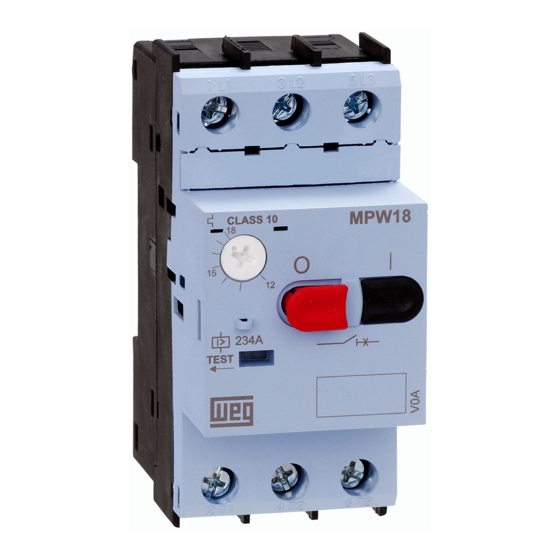
MPW18
MPW18i
2 2
2 2
mm
in
mm
in
/
#1
AC
(
(
DC
(
(
#2
CWC07...16
(
(
ECCMP-C016
AC
CWB9...38
(
(
ECCMP-18B38
AC
#2
ACBS
#1
1 1
CLACK!
1 1
2 X ( M4 X 20 mm)
1.2 Nm
10.6 lb.in
FTBBS
TSB
SCMP
PLMP
PE41 (IP41)
PE41
(IP21)
PE66 (IP66)
mm
in
PHILLIPS #2
BBS
URMP
SRMP
CIC18
FESTPE
FESPPE
FESYPE
FESTPE
FESPPE
PE66
(IP66)
FESYPE
ACBF
Ø2 ...4
Ø0.08...0.16
1 / 2
Advertisement

Related Manuals for WEG ACBS


Summarization of Contents
WEG MPW18/MPW18i Series Overview
General Safety Precautions
Essential safety instructions before installation and maintenance.
Component Identification
Identification of various product components and accessories.
Accessory Installation Examples
Examples of how to install accessory modules like PE41 and PE66.
MPW18/MPW18i Operation and Technical Data
Device Adjustment and Operation
Guidance on adjusting and operating the device.
Tripping Characteristic Curves
Detailed tripping time curves for different pole configurations and sensitivity.
ACBF-11 Auxiliary Contact Block Installation
Installation Procedure
Step-by-step visual guide for installing the ACBF-11 auxiliary contact block.
Product Information and Support
Warranty and European Importer Information
Details on product warranty and contact information for European importers.
ACBS/ACBSD Series Auxiliary Contact Blocks
Model Identification and Wiring Diagrams
Identification of ACBS/ACBSD models and their terminal connections.
Accessory Installation Precautions
Circuit Breaker Disconnection for Accessory Mounting
Ensuring the circuit breaker is off before installing accessories.
ACBS_S and ACBF-11_S Installation Guide
Mounting and Wiring Diagrams
Visual guide for mounting and wiring ACBS_S and ACBF-11_S units.
ACBS_S Dimensions and Terminal Details
Dimensional Drawings
Technical drawings showing the physical dimensions of the ACBS_S unit.
Terminal Connections A and B
Explanation of terminal connections labeled A and B for ACBS_S.
CLT25 Limiter Installation and Usage
Compatibility and Installation Notes
Important notes on using CLT25 with MPW25 and installation steps.
MPW Circuit Breaker Wiring and Mounting
Wiring Configurations
Diagrams illustrating wiring configurations for MPW circuit breakers.
Mounting and Torque Specifications
Guidance on mounting the circuit breaker and required torque values.
CLT32 Limiter Installation and Usage
Compatibility and Installation Notes
Important notes on using CLT32 with MPW25/40 and installation steps.
FME55/FME55-E Front Enclosure Mounting
Front Plate and Indicator Light Installation
Instructions for installing the front plate and indicator light on the FME55/FME55-E.
FME55/FME55-E Enclosure Details
Rotary Handle Locking and Dimensions
Information on locking the rotary handle and physical dimensions of the enclosure.
LPE55/LPE55-E/MLPE55/MLPE55-E Enclosure Mounting
Assembly Steps and Cable Gland Installation
Step-by-step guide for mounting the insulated enclosure and installing cable glands.
LPE55/LPE55-E/MLPE55/MLPE55-E Enclosure Details
Indicator Light and Handle Locking
Instructions for indicator light installation and rotary handle locking.
Enclosure Dimensions
Physical dimensions of the insulated enclosure.
MRX Rotary Handle for Panel Mounting
Compatibility and Panel Mounting
Information on compatibility and installation of the MRX rotary handle on panels.
Panel Cut-out Dimensions
Required dimensions for cutting the panel for handle installation.
MRX Rotary Handle Mounting Options
Locking Features and Panel Drilling
Options for locking the handle and drilling the panel door.
Mounting Methods (Threaded Guide/Screws)
Details on mounting the handle using threaded guide nuts or screws.
RHMP Rotary Handle
Safety and Component Identification
Safety precautions and identification of components for RHMP rotary handle.
RHMP Rotary Handle Assembly and Dimensions
Assembly Procedure
Step-by-step instructions for assembling the RHMP rotary handle.
Dimensions and Panel Cut-out
Physical dimensions and required panel cut-out details for RHMP handle.
TSB Accessory Installation
Compatibility and Installation
Information on TSB accessory compatibility with MPW units and installation steps.
Specific Installation Precautions
Important precautions for correct TSB accessory installation.
TSB Installation and Operation Details
Wiring and Fault Descriptions
Wiring diagram and explanation of fault types (short-circuit, overload).
Mounting Torque and Importer Information
Specifications for mounting torque and list of European importers.
SRMP/URMP Rotary Handle Accessories
Compatibility and Wiring
Compatibility details and wiring diagrams for SRMP/URMP with MPW units.
Operating Voltage and Mounting
Note on operating voltage and general mounting information for SRMP/URMP.
PE55/PE55-E/MPE55/MPE55-E Enclosure Mounting
Assembly Steps and Cable Gland Installation
Step-by-step guide for mounting the insulated enclosure and installing cable glands.
PE55/PE55-E/MPE55/MPE55-E Enclosure Details
Indicator Light and Handle Locking
Instructions for indicator light installation and rotary handle locking.
Enclosure Dimensions
Physical dimensions of the insulated enclosure.
Need help?
Do you have a question about the ACBS and is the answer not in the manual?
Questions and answers