
Related Manuals for WEG SSW900-CRS485-W


Summary of Contents for WEG SSW900-CRS485-W
- Page 1 Motors | Automation | Energy | Transmission & Distribution | Coatings Modbus RTU SSW900-CRS485-W User’s Guide...
- Page 2 Modbus RTU User’s Guide Series: SSW900 Software version: 1.5X Language: English Document: 10004628707 / 05 Build 6066 Publication Date: 09/2022...
- Page 3 Summary of Revisions The information below describes the reviews made in this manual. Version Revision Description V1.0X First edition V1.1X General revision V1.2X General revision V1.3X Parameters related to the SSW900-CETH-W accessory. Parameter for adjusting the contrast of the HMI display. Text corrections. V1.4X C6.2.1, C11.4.
-
Page 4: Table Of Contents
Contents Contents ABOUT THE MANUAL ................. . . ABBREVIATIONS AND DEFINITIONS . - Page 5 Contents 7.4 COMMUNICATION ERRORS ................27 8 STARTUP GUIDE .
-
Page 6: About The Manual
ABOUT THE MANUAL ABOUT THE MANUAL This manual supplies the necessary information for the operation of the SSW900 soft-starter using the Modbus RTU protocol. This manual must be used together with the SSW900 user’s manual and programming manual. ABBREVIATIONS AND DEFINITIONS ASCII American Standard Code for Information Interchange Cycling Redundancy Check... -
Page 7: Main Characteristics
MAIN CHARACTERISTICS 1 MAIN CHARACTERISTICS Below are the main characteristics for Modbus RTU communication of the soft-starter SSW900. • Interface galvanically insulated and with differential signal, providing more robustness against electromagnetic interference. • It allows the device to operate as Modbus RTU slave. •... -
Page 8: Modbus Communication Introduction
MODBUS COMMUNICATION INTRODUCTION 2 MODBUS COMMUNICATION INTRODUCTION The Modbus protocol was initially developed in 1979 by Modicon. Nowadays, it is a widely spread open protocol, used by several manufactures in many equipments. It is a protocol of application layer for communication between devices, especially used by industrial automation systems. -
Page 9: Modbus Rtu
MODBUS COMMUNICATION INTRODUCTION 2.2 MODBUS RTU Two transmission modes are defined in the Modbus protocol specification for the serial interface: ASCII and RTU. These modes define the way the message bytes are transmitted. It is not possible to use the two trans- mission modes in the same network. -
Page 10: Interface Description
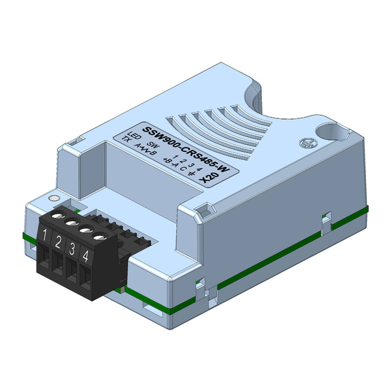
Slot 2 Figure 3.1: Slots for accessories The SSW900 soft-starter uses the RS485 accessory to provide a Modbus RTU interface for communication. Characteristics of this interface are described next. 3.1 RS485 ACCESSORY SSW900-CRS485-W: • Supplied items: – Installation guide. –... -
Page 11: Terminating Resistor
INTERFACE DESCRIPTION Table 3.1: Pin assignment of connector for RS485 (X20) Name Function RxD/TxD positive RxD/TxD negative 0V isolated from the RS485 circuit, used to enable the connection of this point to the reference 0V of the other network de- vices Protective earth Connection to the protective earth, nor-... -
Page 12: Installation Of The Equipment In Network
INSTALLATION OF THE EQUIPMENT IN NETWORK 4 INSTALLATION OF THE EQUIPMENT IN NETWORK For the connection of the soft-starter SSW900 using the RS485 interface, the following points must be observed: 4.1 COMMUNICATION RATE The RS485 interfaces of the SSW900 soft-starter can communicate using the rates defined on the table 4.1. Table 4.1: Supported baud rates Baud Rate 9600 bit/s... -
Page 13: Recommendations For Grounding And Cable Passage
INSTALLATION OF THE EQUIPMENT IN NETWORK Modbus RTU Master Termination Termination Figure 4.1: Modbus RTU network installation example In order to avoid problems with current circulation caused by difference of potential among ground connections, it is necessary that all the devices be connected to the same ground point. The maximum number of devices connected to a single segment of the network is limited to 32. -
Page 14: Status
S STATUS 5 S STATUS Allows viewing of the SSW reading variables. S5 COMMUNICATIONS HMI monitoring parameters of the communication interfaces. For a detailed description, refer to the Anybus-CC, CANopen, DeviceNet, Ethernet and Modbus RTU User’s Manuals of the SSW according to the interface used. S5.1 Status Word .1 SSW 0 ... -
Page 15: S5.3 Value For Outputs
S STATUS Description: Command word of all sources of the SSW. The RUN/STOP and JOG commands of the sources which are not active will be reset. .5 Slot1 Control word via any communication accessory connected to Slot 1. .6 Slot2 Command word via any communication accessory connected to Slot 2. Value/Description Bit 0 0: stopping by ramp. -
Page 16: S5.4 Rs485 Serial
S STATUS S5.4 RS485 Serial .1 Interface Status 0 ... 2 .2 Received Telegram 0 ... 65535 .3 Transmitted Telegram 0 ... 65535 .4 Telegram with Error 0 ... 65535 .5 Reception Errors 0 ... 65535 Description: Status for RS485 accessory, and the protocols using this interface. .1 Interface Status Identify whether the RS485 serial interface board is properly installed, and whether the serial communication presents errors. -
Page 17: Configurations
Protocol Accessory CANopen SSW900-CAN-W DeviceNet SSW900-CDN-N, SSW900-CAN-W EtherNet/IP SSW900-CETH-IP-N, SSW900-CETH-W Modbus RTU SSW900-CRS485-W Modbus TCP SSW900-CMB-TCP-N, SSW900-CETH-W Profibus DP SSW900-CPDP-N PROFINET IO SSW900-CPN-IO-N PROFINET S2 SSW900-CPN-S2-N For further details regarding the SSW configuration to operate these protocols, refer to the SSW Communication Manual. -
Page 18: C8.1.2 Data Write
C CONFIGURATIONS C8.1.1 Data Read C8.1.1.2 Slot 1 Quantity Range: 1 ... 50 Default: 1 Properties: Stopped Description: It sets the number of read words for data communication (inputs for master), from the first word on. C8.1.1 Data Read C8.1.1.3 Slot 2 1st Word Range: 1 ... - Page 19 C CONFIGURATIONS Description: It sets the number of write words for data communication (outputs for master), from the first word on. C8.1.2 Data Write C8.1.2.3 Slot 2 1st Word Range: 1 ... 20 Default: 11 Properties: Stopped Description: It sets the index of the first programmable write word for data communication (outputs for master). C8.1.2 Data Write C8.1.2.4 Slot 2 Quantity Range:...
-
Page 20: C8.2 Rs485 Serial
C CONFIGURATIONS Description: Select the net address of other parameter, which content will be available as writing data for fieldbus interfaces (outputs: received from master). The data size of the referenced parameter must be considered. If data size is bigger than 16 bits, the next data write word configuration must be set to the same net address. -
Page 21: C8.2.5 Timeout
C CONFIGURATIONS Description: Select the number of data bits, parity and stop bits of the serial interface bytes. This configuration must be identical for all the devices connected to the network. Indication Description 0 = 8 bits, no, 1 8 bits, without parity, 1 stop bit. 1 = 8 bits, even,1 8 bits, with even parity, 1 stop bit. - Page 22 C CONFIGURATIONS ✓ NOTE! The alarm action will only have a function if the timeout tripping mode C8.2.5.1 is programmed for Alarm A128. C8.2.5 Timeout C8.2.5.3 Timeout Range: 0.0 ... 999.9 s Default: 0.0 Properties: Description: Maximum time without communication. SSW900 | 22...
-
Page 23: Operation In The Modbus Rtu Network - Slave Mode
OPERATION IN THE MODBUS RTU NETWORK – SLAVE MODE 7 OPERATION IN THE MODBUS RTU NETWORK – SLAVE MODE The SSW900 soft-starter has the following characteristics when operated as a slave in Modbus RTU network: • Network connection via RS485 serial interface. •... -
Page 24: Memory Markers
OPERATION IN THE MODBUS RTU NETWORK – SLAVE MODE • S5.2.5 (holding register address 685): Command Word Slot1. • S5.2.6 (holding register address 686): Command Word Slot2. Refer to the item 10 for a complete parameter list of the equipment. ✓... - Page 25 OPERATION IN THE MODBUS RTU NETWORK – SLAVE MODE is shared between the two Slots. To map an object in the reading area, follow the steps below. 1. Configure parameter C8.1.1.1 (Slot 1) or C8.1.1.3 (Slot 2). Those parameters indicate which of the reading words starts the input area for the specific Slot.
-
Page 26: Output Words
OPERATION IN THE MODBUS RTU NETWORK – SLAVE MODE 7.2.5 Output Words The SSW900 soft-starter has a writing area with 20 16-bit words available for cyclic data exchange of commu- nication networks. The data available in the write area (Output) is received from the network master. This area is shared between the two Slots. -
Page 27: Data Access
OPERATION IN THE MODBUS RTU NETWORK – SLAVE MODE 7.3 DATA ACCESS The Modbus protocol allows the access only by bits or by 16-bit registers. To make it possible to write or read a block of more than 2 registers without an error return even if there is an invalid register in the selected range, the following definitions have been used: •... -
Page 28: Startup Guide
STARTUP GUIDE 8 STARTUP GUIDE The main steps to start up the SSW900 soft-starter in Modbus TCP network are described below. These steps represent an example of use. Check out the specific chapters for details on the indicated steps. 8.1 INSTALLING THE ACCESSORY 1. - Page 29 STARTUP GUIDE • Parameters S5.4.2 and S5.4.3 indicate, respectively, the number of Modbus RTU telegrams received and transmitted by the slave. • Parameters S5.4.4 and S5.4.5 indicate communication errors detected by the slave. The master of the network must also supply information about the communication with the slave. SSW900 | 29...
-
Page 30: Faults And Alarms
FAULTS AND ALARMS 9 FAULTS AND ALARMS Fault/Alarm Description Possible Causes F128/A128: Serial Communication It indicates that the SSW stopped receiving valid - Check network installation, broken cable or Timeout telegrams for a period longer than the setting fault/poor contact on the connections with the net- (C8.2.5.3). -
Page 31: 10Quick References
QUICK REFERENCES 10 QUICK REFERENCES 10.1 PARAMETER STRUCTURE Level 1 Level 2 Level 3 Page Status Measurements S1.1 Current S1.2 Main Line Voltage S1.3 Output Voltage S1.4 SCR Blocking Voltage S1.5 Output Power & P.F. S1.6 P.L.L. S1.7 Motor Torque S1.8 Control Voltage S2.1... - Page 32 QUICK REFERENCES Level 1 Level 2 Level 3 Page Configurations Starting and Stopping Nominal Motor Data LOC/REM Selection C4.1 Digital Inputs C4.2 Digital Outputs C4.3 Analog Output Protections C5.1 Voltage Protections C5.2 Current Protections C5.3 Torque Protections C5.4 Power Protections C5.5 Phase Sequence C5.6...
-
Page 33: Parameters
10.2 PARAMETERS Table 10.2: Characteristics of the parameters for the communication protocol Parameter Description Range of values Decimal Net Id Size Qty mapped places words S1 Status\Measurements S1.1 Current S1.1.1 R Phase 0.0 to 14544.0 A 32bit S1.1.2 S Phase 0.0 to 14544.0 A 32bit S1.1.3... - Page 34 Parameter Description Range of values Decimal Net Id Size Qty mapped places words S1.7.1 Motor %Tn 0.0 to 999.9 % 16bit S1.8 Control Voltage S1.8.1 Input 0.0 to 999.9 V 16bit S1.8.2 0.00 to 9.99 V 16bit S1.8.3 +12V 0.0 to 99.9 V 16bit S1.8.4 +Vbat...
- Page 35 Parameter Description Range of values Decimal Net Id Size Qty mapped places words 11 = Start Delay 12 = Re-start Delay 13 = General Disabled 14 = Configuration S3.1.2 Active Command Source enum 0 = HMI Keys LOC 1 = HMI Keys REM 2 = DIx LOC 3 = DIx REM 4 = USB LOC...
- Page 36 Parameter Description Range of values Decimal Net Id Size Qty mapped places words Bit 4 = Reset Needs Bit 5 = Copy HMI Bit 6 = Test Mode Bit 7 ... 15 = Reserved S3.2 Software Version S3.2.1 Package 0.00 to 99.99 16bit S3.2.2 Details...
- Page 37 Parameter Description Range of values Decimal Net Id Size Qty mapped places words S3.5.1 Slot 1 enum 0 = Without 1 = Anybus-CC 2 = RS-485 3 = PT100 4 = I/Os Exp. 5 = Profibus 6 = CAN 7 = Ethernet 8 = External Current Acqu.
- Page 38 Parameter Description Range of values Decimal Net Id Size Qty mapped places words Bit 6 = Bypass Bit 7 = Ramp Down Bit 8 = Remote Bit 9 = Braking Bit 10 = FWD/REV Bit 11 = Reverse Bit 12 = Ton Bit 13 = Toff Bit 14 = Alarm Bit 15 = Fault...
- Page 39 Parameter Description Range of values Decimal Net Id Size Qty mapped places words Bit 0 = Start/Stop Bit 1 = Gener. Enabled Bit 2 = JOG Bit 3 = FWD/REV Bit 4 = LOC/REM Bit 5 ... 6 = Reserved Bit 7 = Reset Bit 8 ...
- Page 40 Parameter Description Range of values Decimal Net Id Size Qty mapped places words S5.4.4 Telegram with Error 0 to 65535 16bit S5.4.5 Reception Errors 0 to 65535 16bit S5.5 Anybus-CC S5.5.1 Identification enum 0 = Disabled 1 ... 15 = Reserved 16 = Profibus DP 17 = DeviceNet 18 = Reserved...
- Page 41 Parameter Description Range of values Decimal Net Id Size Qty mapped places words 0 = Disabled 1 = Auto-baud 2 = CAN Enabled 3 = Warning 4 = Error Passive 5 = Bus Off 6 = No Bus Power S5.7.2 Received Telegram 0 to 65535 16bit...
- Page 42 Parameter Description Range of values Decimal Net Id Size Qty mapped places words S5.8.3 EIP Master Status enum 0 = Run 1 = Idle S5.8.4 EIP Communication Status enum 0 = Disabled 1 = No connection 2 = Connected 3 = Timeout in I/O Connection 4 = Duplicated IP S5.8.5 Interface Status...
- Page 43 Parameter Description Range of values Decimal Net Id Size Qty mapped places words S6.4.6 User #6 -10000 to 10000 1120 s32bit S6.4.7 User #7 -10000 to 10000 1122 s32bit S6.4.8 User #8 -10000 to 10000 1124 s32bit S6.4.9 User #9 -10000 to 10000 1126 s32bit...
- Page 44 Parameter Description Range of values Decimal Net Id Size Qty mapped places words S6.4.48 User #48 -10000 to 10000 1204 s32bit S6.4.49 User #49 -10000 to 10000 1206 s32bit S6.4.50 User #50 -10000 to 10000 1208 s32bit D1 Diagnostics\Fault D1.1 Actual D1.1.1 Fxxx...
- Page 45 Parameter Description Range of values Decimal Net Id Size Qty mapped places words ◦ D5.2.2 Channel 2 -20 to 260 s16bit ◦ D5.2.3 Channel 3 -20 to 260 s16bit ◦ D5.2.4 Channel 4 -20 to 260 s16bit ◦ D5.2.5 Channel 5 -20 to 260 s16bit ◦...
- Page 46 Parameter Description Range of values Decimal Net Id Size Qty mapped places words C1.17 End Stop Torque 10 to 100 % 8bit C1.18 Minimum Stop Torque 10 to 100 % 8bit C1.19 Min. Stop Torque Time 1 to 99 % 8bit C2 Configurations\Nominal Motor Data C2.1...
- Page 47 Parameter Description Range of values Decimal Net Id Size Qty mapped places words C4 Configurations\I/O C4.1 Digital Inputs C4.1.1 enum 0 = Not Used 1 = Start / Stop 2 = Start (3 Wires) 3 = Stop (3 Wires) 4 = General Enable 5 = LOC / REM 6 = JOG 7 = FWD / REV...
- Page 48 Parameter Description Range of values Decimal Net Id Size Qty mapped places words 8 = No External Fault 9 = No External Alarm 10 = Brake 11 = Reset 12 = Load User 1/2 13 = Reserved 14 = Emergency Start 15 ...
- Page 49 Parameter Description Range of values Decimal Net Id Size Qty mapped places words 3 = Stop (3 Wires) 4 = General Enable 5 = LOC / REM 6 = JOG 7 = FWD / REV 8 = No External Fault 9 = No External Alarm 10 = Brake 11 = Reset...
- Page 50 Parameter Description Range of values Decimal Net Id Size Qty mapped places words 11 = SoftPLC 12 = Communication 13 = I motor % > Value 14 = Breaker Shunt Trip C4.2.3 enum 0 = Not Used 1 = Running 2 = Full Voltage 3 = Bypass 4 = Not Used...
- Page 51 Parameter Description Range of values Decimal Net Id Size Qty mapped places words 4 = 0 to 10V 5 = 10V to 0 C5 Configurations\Protections C5.1 Voltage Protections C5.1.1 Motor Undervoltage C5.1.1.1 Mode enum 0 = Inactive 1 = Fault F002 2 = Alarm A002 C5.1.1.2 Level...
- Page 52 Parameter Description Range of values Decimal Net Id Size Qty mapped places words C5.2.3.1 Mode enum 0 = Inactive 1 = Fault F074 2 = Alarm A074 C5.2.3.2 Level 0 to 30 %In 8bit C5.2.3.3 Time 1 to 99 s 8bit C5.3 Torque Protections...
- Page 53 Parameter Description Range of values Decimal Net Id Size Qty mapped places words C5.6 Bypass Protections C5.6.1 Undercurrent enum 0 = Inactive 1 = Fault F076 C5.6.2 Overcurrent enum 0 = Inactive 1 = Fault F063 C5.6.3 Closed enum 0 = Inactive 1 = Fault F077 C5.7 Time Protections...
- Page 54 Parameter Description Range of values Decimal Net Id Size Qty mapped places words C5.8.6 Ch2 Overtemperature C5.8.6.1 Mode enum 0 = Fault F102 1 = Alarm A102 2 = F102 and A102 ◦ C5.8.6.2 Fault Level 0 to 250 8bit ◦...
- Page 55 Parameter Description Range of values Decimal Net Id Size Qty mapped places words ◦ C5.8.12.4 Alarm Reset 0 to 250 8bit C5.8.13 Ch5 Installed Sensor C5.8.13.1 Mode 1010 enum 0 = Off 1 = On 2 = On Stator C5.8.14 Ch5 Sensor Fault C5.8.14.1 Mode...
- Page 56 Parameter Description Range of values Decimal Net Id Size Qty mapped places words 1 = Fault F005 2 = Alarm A005 3 = F005 and A005 C5.9.3 Alarm Level 0 to 100 % 8bit C5.9.4 Alarm Reset 0 to 100 % 8bit C5.9.5 Motor Temperature...
- Page 57 Parameter Description Range of values Decimal Net Id Size Qty mapped places words C5.10.2 Motor On enum 0 = Inactive 1 = Fault F020 C5.11 Fault Auto-Reset C5.11.1 Mode enum 0 = Off 1 = On C5.11.2 Time 3 to 600 s 16bit C6 Configurations\HMI C6.1...
- Page 58 Parameter Description Range of values Decimal Net Id Size Qty mapped places words C6.6.2 Alarm Action enum 0 = Indicates Only 1 = Ramp Stop 2 = General Disable 3 = Change to LOC 4 = Change to REM C6.6.3 Time 1 to 999 s 16bit...
- Page 59 Parameter Description Range of values Decimal Net Id Size Qty mapped places words C8.1.1.3 Slot 2 1st Word 1 to 50 8bit C8.1.1.4 Slot 2 Quantity 1 to 50 8bit C8.1.1.5 Word #1 0 to 65535 1300 16bit C8.1.1.6 Word #2 0 to 65535 1301 16bit...
- Page 60 Parameter Description Range of values Decimal Net Id Size Qty mapped places words C8.1.1.45 Word #41 0 to 65535 1340 16bit C8.1.1.46 Word #42 0 to 65535 1341 16bit C8.1.1.47 Word #43 0 to 65535 1342 16bit C8.1.1.48 Word #44 0 to 65535 1343 16bit...
- Page 61 Parameter Description Range of values Decimal Net Id Size Qty mapped places words C8.2.3 Baud Rate enum 0 = 9600 bits/s 1 = 19200 bits/s 2 = 38400 bits/s 3 = 57600 bits/s C8.2.4 Bytes Config. enum 0 = 8 bits, no, 1 1 = 8 bits, even,1 2 = 8 bits, odd, 1 3 = 8 bits, no, 2...
- Page 62 Parameter Description Range of values Decimal Net Id Size Qty mapped places words 1 = 128.0.0.0 2 = 192.0.0.0 3 = 224.0.0.0 4 = 240.0.0.0 5 = 248.0.0.0 6 = 252.0.0.0 7 = 254.0.0.0 8 = 255.0.0.0 9 = 255.128.0.0 10 = 255.192.0.0 11 = 255.224.0.0 12 = 255.240.0.0...
- Page 63 Parameter Description Range of values Decimal Net Id Size Qty mapped places words 3 = Change to LOC 4 = Change to REM C8.3.9.3 Modbus TCP Timeout 0.0 to 999.9 s 16bit C8.3.10 Off Line Error C8.3.10.1 Mode enum 0 = Inactive 1 = Fault F129 2 = Alarm A129 C8.3.10.2...
- Page 64 Parameter Description Range of values Decimal Net Id Size Qty mapped places words 2 = General Disable 3 = Change to LOC 4 = Change to REM C8.5 Ethernet C8.5.1 IP Address Config enum 0 = Parameters 1 = DHCP C8.5.2 IP Address 0.0.0.0 to 255.255.255.255...
- Page 65 Parameter Description Range of values Decimal Net Id Size Qty mapped places words C8.5.5 MBTCP: TCP Port 0 to 65535 16bit C8.5.7 EIP Data Profile enum 0 ... 9 = Reserved 10 = 110/160-Configurable I/O C8.5.9 Modbus TCP Error C8.5.9.1 Mode enum 0 = Inactive...
- Page 66 Parameter Description Range of values Decimal Net Id Size Qty mapped places words 4 = 45 A 5 = 61 A 6 = 85 A 7 = 105 A 8 = 130 A 9 = 171 A 10 = 200 A 11 = 255 A 12 = 312 A 13 = 365 A...
- Page 67 Parameter Description Range of values Decimal Net Id Size Qty mapped places words 4 = I/Os Exp. 5 = Profibus 6 = CAN 7 = Ethernet 8 = External Current Acqu. C9.4 Fan Configuration C9.4.1 Mode enum 0 = Always Off 1 = Always On 2 = Controlled C10 Configurations\Load / Save Parameters...
- Page 68 Parameter Description Range of values Decimal Net Id Size Qty mapped places words 0 = No 1 = Yes C11 Configurations\SoftPLC C11.1 Mode 1101 enum 0 = Stop Program 1 = Run Program C11.2 Action App. Not Running 1103 enum 0 = Inactive 1 = Alarm A708 2 = Fault F708...
- Page 69 Parameter Description Range of values Decimal Net Id Size Qty mapped places words C11.3.31 User #31 -10000 to 10000 1170 s32bit C11.3.32 User #32 -10000 to 10000 1172 s32bit C11.3.33 User #33 -10000 to 10000 1174 s32bit C11.3.34 User #34 -10000 to 10000 1176 s32bit...
- Page 70 QUICK REFERENCES Table 10.3: Description of the parameter data types Data Type Description enum Enumerated type (unsigned 8-bit) contains a list of values with function description for each item. 8bit Unsigned 8-bit integer, ranges from 0 to 255. 16bit Unsigned 16-bit integer, ranges from 0 to 65,535. s16bit Signed 16-bit integer, ranges from -32,768 to 32,767.
- Page 71 WEG Drives & Controls - Automation LTDA. Jaraguá do Sul - SC - Brazil Phone 55 (47) 3276-4000 - Fax 55 (47) 3276-4020 São Paulo - SP - Brazil Phone 55 (11) 5053-2300 - Fax 55 (11) 5052-4212 automacao@weg.net www.weg.net...
Need help?
Do you have a question about the SSW900-CRS485-W and is the answer not in the manual?
Questions and answers