Sign In
Upload
Download
Table of Contents
Contents
Add to my manuals
Delete from my manuals
Share
URL of this page:
HTML Link:
Bookmark this page
Add
Manual will be automatically added to "My Manuals"
Print this page
×
Bookmark added
×
Added to my manuals
Manuals
Brands
SystemBase Manuals
Media Converter
Multi-4U Ver1.7
User manual
SystemBase Multi-4U Ver1.7 User Manual
Usb to serial
Hide thumbs
1
2
3
Table Of Contents
4
5
6
7
8
9
10
11
12
13
14
15
16
17
18
19
20
21
22
23
24
25
26
27
28
29
30
31
32
33
34
35
36
37
38
39
40
41
42
43
44
45
46
47
48
49
50
51
52
53
54
55
56
57
58
59
60
61
62
63
page
of
63
Go
/
63
Contents
Table of Contents
Bookmarks
Table of Contents
Table of Contents
About Multiport(Multi-N) USB Series
Multiport USB Specifications
About Latching USB
Connectivity Method
Rs232
Rs485
Rs422
Termination Resistor
Multi-1/USB Ver4.0
Specification
RS232 Model
RS422, RS485 Model
Multi-2/USB Ver4.0
Specification
RS232 Model
RS422, RS485 Model
Multi-4/USB Ver4.0
Specification
RS232 Model
RS422, RS485 Model
Multi-4U Ver1.7
Specification
RS232 Model
RS422, RS485 Model
Multi-8U Ver1.7
Specification
RS232 Model
RS422/RS485 Model
Multi-4U/8U V1.6
Specification
RS232 Model
Combo (RS422/RS485) Model
Manually Installing Windows Device Driver
Automatic Driver Installation in Windows
Windows Device Driver Setup
Manually Removing Windows Device Driver
Automatic Driver Uninstallation in Windows
Serial Port Sorting Program (Usbserial_Remap)
Multi-4U/8U Version History
Advertisement
Quick Links
Download this manual
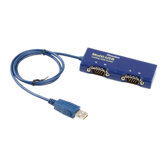
USB to Serial
User Manual
Version 3.05.1 2020/11/20
www.sysbas.com
1
Table of
Contents
Previous
Page
Next
Page
1
2
3
4
5
Advertisement
Table of Contents
Need help?
Do you have a question about the Multi-4U Ver1.7 and is the answer not in the manual?
Ask a question
Questions and answers
Related Manuals for SystemBase Multi-4U Ver1.7
Media Converter SystemBase Multi-8U Ver1.7 User Manual
Usb to serial (63 pages)
Media Converter SystemBase Multi-4U V1.6 User Manual
Usb to serial (63 pages)
Media Converter SystemBase Multi-8U V1.6 User Manual
Usb to serial (63 pages)
Media Converter SystemBase Multi-1/USB Ver4.0 User Manual
Usb to serial (63 pages)
Media Converter SystemBase SerialGate 2000 Series User Manual
(88 pages)
Media Converter SystemBase BT-232 User Manual
Rf/serial(rs232) converter (2 pages)
Media Converter SystemBase SWIFIALLV10 User Manual
(16 pages)
SystemBase WCS-232 v4.0 - Wireless/Serial(RS232) Converter Manual
(article)
Media Converter SystemBase CS-LAN User Manual
(25 pages)
Media Converter SystemBase SerieslGate SG-1010/232 User Manual
(110 pages)
Media Converter SystemBase TALUS User Manual
(28 pages)
Media Converter SystemBase sLAN/all-PoE User Manual
(28 pages)
This manual is also suitable for:
Multi-8u ver1.7
Multi-4u v1.6
Multi-8u v1.6
Multi-8/usb combo v1.6
Multi-4/usb combo v1.6
Multi-1/usb ver4.0
...
Show all
Multi-2/usb ver4.0
Multi-4/usb ver4.0
Table of Contents
Print
Rename the bookmark
Delete bookmark?
Delete from my manuals?
Login
Sign In
OR
Sign in with Facebook
Sign in with Google
Upload manual
Upload from disk
Upload from URL


Need help?
Do you have a question about the Multi-4U Ver1.7 and is the answer not in the manual?
Questions and answers