
Subscribe to Our Youtube Channel
Related Manuals for Daikin LFMNS0150AXV1


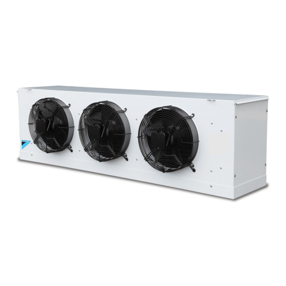
Summary of Contents for Daikin LFMNS0150AXV1
- Page 1 COMMERCIAL REFRIGERATION UNIT COOLER MEDIUM & LOW TEMPERATURE OPERATING AND INSTALLATION MANUAL...
-
Page 2: Table Of Contents
TABLE OF CONTENTS Page Unit Information and Dimensions Nomenclature Product Features Unit Dimension Exploded View General Health and Safety 2.1 General Information Specification 3.1 General 3.2 Capacity Table Unit location and Mounting Unit Location Mounting Piping Installation Refrigerant Piping Evacuation and Leak test Drain Pipe Superheat Electrical... -
Page 3: Nomenclature
UNIT INFORMATION Nomenclature 0150 Power Supply: V1 – 1ph/50Hz/220~240V Y1 – 3ph/50Hz/380~415V Production Plant Generation: A- 1 version Nominal Cooling Capacity: 0150- 1.5kW Type of Refrigerant: P- R407C S- R404A Bills of Material: MN – Medium Temperature without heater LH – Low Temperature with heater Unit Category: R: Outdoor unit F: Indoor unit... -
Page 4: Unit Dimension
Unit Dimension Model: LFMNS0150AXV1, LFMNS0400AXV1, LFLHS0150AXV1, LFLHS0200AXV1 Model: LFMNS0600AXV1, LFMNS0800AXV1, LFLHS0320AXV1, LFLHS0400AXV1 Model: LFMNS0980AXV1, LFMNS1400AXV1, LFLHS0480AXV1, LFLHS0600AXV1 0-UC 13-FEB 18-2 Page 4... -
Page 5: Exploded View
Exploded View Medium Temperature Application LFMNS0150AXV1, LFMNS0400AXV1 LFMNS0600AXV1, LFMNS0800AXV1 0-UC 13-FEB 18-2 Page 5... - Page 6 LFMNS0980AXV1, LFMNS1400AXV1 EVAPORATOR COIL DRAIN PAN PANEL TOP PANEL SIDE PANEL RIGHT PANEL LEFT HANGER ADAPTOR DRAIN PAN FITTING CONTROL BOX COVER TERMINAL BLOCK 0-UC 13-FEB 18-2 Page 6...
- Page 7 Low Temperature Application LFLHS0150AXV1, LFLHS0200AXV1 LFLHS0320AXV1, LFLHS0400AXV1 0-UC 13-FEB 18-2 Page 7...
- Page 8 LFLHS0480AXV1, LFLHS0600AXV1 DEFROST HEATER EVAPORATOR COIL DRAIN PAN PANEL TOP PANEL FRONT PANEL SIDE PANEL RIGHT PANEL LEFT HANGER HEATER CLAMP ADAPTOR DRAIN PAN FITTING CONTROL BOX COVER TERMINAL BLOCK 0-UC 13-FEB 18-2 Page 8...
-
Page 9: General
General Upon receive of the products, 1. Please ensure: • The pipework should show no signs of damage • The fan/ fan motor terminals box is not cracked or showing signs of obvious damage • The electrical screw terminals in control panels and motor mountings should be checked for security. 2. - Page 10 During Installation and subsequent maintenance Installation and maintenance are to be performed only by qualified personnel who are familiar with • local codes and regulations, and experienced with this type of equipment. If lifting equipment is required, ensure that it is suitable for purpose, certificated and that the operatives •...
-
Page 11: Specification
3 SPECIFICATION General (a) Medium Temperature LFMNS0150AX LFMNS0400AX LFMNS0600AX LFMNS0800AX LFMNS0980AX LFMNS1400AX Model 8.05 14.2 Capacity Sound Pressure dB(A) Level Power supply 230/1/50 230/1/50 230/1/50 230/1/50 230/1/50 230/1/50 (V/Ph/Hz) Size L/W/H 1214 x 554 x 1214 x 554 x 1671 x 556 x 1671 x 556 x 760 x 554 x 515 760 x 554 x 515... - Page 12 (b) Low Temperature LFLHS0150AX LFLHS0200AX LFLHS0320AX LFLHS0400AX LFLHS0480AX LFLHS0600AX Model Capacity Sound Pressure dB(A) Level Power supply 230/1/50 230/1/50 230/1/50 230/1/50 230/1/50 230/1/50 (V/Ph/Hz) Size L/W/H 1214 x 554 x 1214 x 554 x 1671 x 556 x 1671 x 556 x 760 x 554 x 515 760 x 554 x 515 (mm/mm/mm)
-
Page 13: Capacity Table
Capacity Table (a) Medium Temperature Refrigerant Refrigerant R404A R134a Model Model LFMNS0150AXV1 LFMNS0150AXV1 1.48 1.54 1.66 1.79 1.35 1.51 1.63 1.50 1.37 LFMNS0400AXV1 LFMNS0400AXV1 3.85 3.90 4.01 4.63 3.51 3.55 3.65 3.91 4.21 LFMNS0600AXV1 LFMNS0600AXV1 5.83 5.90 6.07 6.58 7.05 5.37... -
Page 14: Unit Location And Mounting
Mounting Daikin unit coolers come with mounting holes that can be fixed with the use of M8 or M10 bolts and nuts. The unit must be installed in a level manner, to ensure water condensation can be properly drain out. -
Page 15: Piping Installation
PIPING INSTALLATION Refrigerant pipe connection Refrigerant pipe connections should be installed in accordance with all the applicable codes and using good refrigeration practices. Suction lines should be properly insulated to prevent sweating and ensure only superheated vapor is returned to compressor suction. During brazing, the system should be purged with nitrogen first, to prevent oxidation. -
Page 16: Electrical
The wiring diagram for each unit is located on the inside of the panel door of the control box. The unit must be grounded. Model Heater Removal Length (mm) LFMNS0150AXV1 LFMNS0400AXV1 LFLHS0150AXV1 LFLHS0200AXV1 LFMNS0600AXV1... -
Page 17: Earth Wiring
Earth Wiring Units must be earthed and no maintenance work should be attempted prior to disconnecting the electrical supply. Installation of earth wire should be made to earth screw before connecting the live wires. The earth wire shall be slacked with longer length as shown in below diagram. WARNING Please check electrical safety (leakage current, withstand voltage, earth continuity) after connected to heaters, fuse, and timers. -
Page 18: Wiring Diagram
6.3 Wiring Diagram REMARK: Heater is only provided for low temperature model only. (a) LFMNS0150AXV1; LFMNS0400AXV1; LFLHS0150AXV1; LFLHS0200AXV1 ( b ) LFMNS0600AXV1; LFMNS0800AXV1; LFLHS0320AXV1; LFLHS0400AXV1 0-UC 13-FEB 18-2 Page 18... - Page 19 (c) LFMNS0980AXV1; LFMNS1400AXV1; LFLHS0480AXV1; LFLHS0600AXV1 0-UC 13-FEB 18-2 Page 19...
-
Page 20: Start Up
START UP Pre-start up After the installation is completed, a review of the following items should be performed before the system is placed into operation: Check electrical connections, fan motors, grills and all other fasteners for tightness. Be sure the thermostatic expansion valve bulb is properly located, strapped and insulated. -
Page 21: Troubleshooting Chart
TROUBLESHOOTING CHART Table 1: TROUBLESHOOTING CHART PROBLEM POSSIBLE CAUSES CORRECTIVE ACTION Excessive buildup of Defrost time is too short. Extend defrost time on timer. frost on coil. Too high humidity in room. Limit access to cooler; do not keep doors open during stocking. Change to bigger capacity or add Heater capacity is too small.
Need help?
Do you have a question about the LFMNS0150AXV1 and is the answer not in the manual?
Questions and answers