
Related Manuals for Daikin LXE10E Series


Summary of Contents for Daikin LXE10E Series
- Page 1 Marine type Container Refrigeration Unit Service Manual DAIKIN CONTAINER LXE10E100 or later LXE10E-A (DECOSⅢe) TR 08-03B...
- Page 2 Please read the contents of this manual prior to operation of the unit. This booklet will provide you with the minimum necessary information required to operate the Daikin refrigerated unit LXE10E100 or later equipped with the new controller DECOSⅢe. It covers all of the unit's...
- Page 3 CONTENTS SAFETY PRECAUTIONS 3.4 Back up Battery...........3-29 • Danger ..............4 3.4.1 Specifications ........3-29 • Warning..............5 3.4.2 Function..........3-29 • Caution..............6 3.4.3 Checking the remaining battery voltage ..3-29 1. INTRODUCTION..........1-1 3.4.4 Battery replacement 1.1 Operation range ..........1-1 (Rechargeable battery) ......3-30 1.2 Basic names of components ......1-1 3.5 Information interchange with personal computer...3-34...
- Page 4 7.5 Temperature conversion table and temperature 5.4 Ventilator outlet opening detection (FA sensor) ...5-8 sensor (DCHS) characteristics table....7-3 5.5 Daikin Temperature Management System (optional) ..5-11 7.6 High and low pressure sensor characteristics table..7-4 5.6 Automatic Setpoint Change: ASC (optional) ..5-13 7.7 HFC134a, temperature-vapor pressure...
- Page 5 SAFETY PRECAUTIONS Always observe the following points before operating or inspecting a unit. DANGER Always shut off the main power supply of the facility before disconnecting the power plug. Always turn off the main power supply of the facility before inspecting the interior of the control box.
- Page 6 WARNING Do not touch the condenser fan while power to the unit is ON. Before removing the condenser fan cover, turn off the circuit breaker and disconnect the power plug. During air-cooled operation : Condenser fan may start and stop automatically for the refrigerant high pressure control.
- Page 7 CAUTION Before starting the unit, run the generator. Securely close the control box cover. Otherwise, it will allow water entry. Control box cover Quick-lock lever Temperature Recorder (OPTION) Temperature recorder box cover...
- Page 8 CAUTION Wash the refrigeration unit with fresh water at PTI. 1. Carefully flush the external condenser with fresh water to remove the salt that sticks to it. 2. Corrosive gases generated from the cargo may corrode the copper pipes and aluminium fin of the internal evaporator. Therefore, wrap up the cargo properly to prevent such corrosion.
- Page 9 If any other refrigerant not specified is charged, it may cause problems with the unit. Use only Daikin specified refrigerant oil (IDEMITSU, Daphne Hermetic Oil FVC46D). If any other refrigerating machine oil not specified is charged, it may cause problems with the unit.
- Page 10 CLASS 1 PRODUCT SPECIFIED BY THE LAW CONCERNING THE RECOVERY AND DESTRUCTION OF FLUOROCARBONS OF FLUOROCARBONS HFC IS USED FOR THIS PRODUCT AS A REFRIGERANT. (1) EMISSION OF FLUOROCARBONS INTO THE ATOMOSPHERE WITHOUT PERMISSION IS PROHIBITED. (2) RECOVERY OF FLUOROCARBONS IS MANDATORY WHEN SCRAPPING AND SERVICING THIS PRODUCT.
- Page 11 1. INTRODUCTION 1.1 Operation range Use the units within the following range. Item Operation range External temperature range -30˚C to +50˚C (-22˚F to + 122˚F) Internal temperature range -30˚C to +30˚C (-22˚F to + 86˚F) 50Hz: 380V/400V/415V, 60Hz: 440V/460V Voltage Voltage fluctuation rate should be within ±10%...
- Page 12 1.3 Basic operation of refrigeration unit 1.3.1 Starting operation (1) Connect the power plug to the power supply. Insert the plug q suited to the power source voltage, and fasten the plug firmly. (2) Turn on circuit breaker w after checking that the power supply switch is turned on (Outside of the unit).
- Page 13 1.3.2 Check items during operation Check items(precautions) Method of check 1. Check the compressor, fan, pipes, etc. for abnormal Visual and sound check noise and vibration. Visual check by using the moisture indicator 2. Check the refrigerant for shortage.
- Page 14 1.3.4 Adjust the ventilation CAUTION Adjust the opening of the ventilation according to the cargo. Keep the ventilation closed when ventilation is not necessary or during transportation of the frozen cargo. Set the arrow mark of the handle to "CLOSE"...
- Page 15 2. GENERAL DESCRIPTION 2.1 Main specifications Model LXE10E100 or later Item Condenser cooling system Air cooled type Controller DECOS3e Power supply AC 3-phase 380V/400V/415V 50Hz, 440V/460V 60Hz Compressor Full hermetic scroll type (Motor output: 5.5kW) Evaporator Cross fin coil type...
- Page 16 2.2 Names of components 2.2.1 Outside ●LXE10E Refer to the next page for detail of solenoid valves 2 2 2 1 2 0 1 7 1 6 Refer to page 2-4 for detail of compressor and refrigerant control devices...
- Page 17 ●LXE10E · Detail of solenoid valves (option) [Valve] BSV :Discharge gas bypass Solenoid Valve DSV :Defrost Solenoid Valve DPR :Discharge Pressure Regulator Valve :Electronic Expantion Valve ESV :Economizer Solenoid Valve HSV :Hot gas Solenoid Valve ISV :Injection Solenoid Valve...
- Page 18 Solenoid valve and activation BSV : Discharge gas by-pass solenoid valve BSV bypasses discharge gas to the suction side of the compressor to maintain low pressure at low outside temperatures. DSV : Defrost solenoid valve DSV supplies discharge gas (hot gas) from the compressor to the evaporator to defrost.
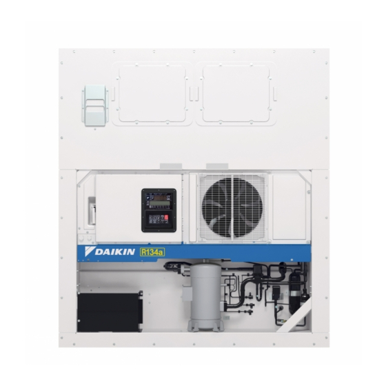
- Page 19 2.2.2 Inside ●LXE10E USDA receptacle PC port receptacle q Evaporator fan motor (EFM) u USDA receptacle [Optional] w Evaporator Lateral and rear type depending on the e Supply air temperature sensor (SS) models i PC port receptacle Data recorder supply air temperature sensor (DSS)
- Page 20 · Inside Detail HuS (optional) RS/DRS/RRS Evaporator Drain Pan Heater ※Reheater coil for Dehumidification Control (optional) [Sensor] DRS:Return Air Temperature Sensor for Datacorder DSS:Supply Air Temperature Sensor for Datacorder EIS :Evaporator Inlet Temperature Sensor EOS:Evaporator Outlet Temperature Sensor HuS :Humidity Sensor (Optional)
- Page 21 2.2.3 Control box ●Operation panel ●Inside of the control box (Outside of the control box) ⑨ ⑩ ⑪ ⑫ ⑬ ⑭ ⑮ ⑯ ① ⑧ ② ⑦ ⑥ ⑤ ③ Front ⑳ ⑲ ⑰ ④ ⑱ Rear q Controller operation panel...
- Page 22 · Control box Inside detail MODEM CONTROLLER (Modem located inward) (optional) (DECOS3e) PCC1 PCC2 BATTERY Tr1(EC5 located inward) (9V dry cell or rechargeable battery) (400V→24V, 13V) [Control Box] BATTERY :Back-up Battery :Circuit Breaker :Magnetic Contactor, Compressor :PT/CT Board :Magnetic Contactor, Evaporator Fan Motor, High Speed...
- Page 23 · Control box Inside detail EC1 (CPU board) Battery circuit board For sensor extension LED101 (Red) HuS (optional) LPT, HPT EC1 (CPU board) CN44 CN46 CN42 LED1 (Green) (I/O board) (optional) (PT/CT board) CN43 (DISPLAY board) CN47 CTS/USDA DRS, EIS, EOS,...
- Page 24 2.3 Set point of protection devices Device name Actuation Set point Detection method Symbol High-pressure switch 2400kPa (24.47kg/cm High-pressure switch 1900kPa (19.37kg/cm High-pressure control for Condenser fan 800kPa (8.2kg/cm High-pressure transducer 1000kPa (10.2kg/cm ※1 Discharge gas Pull down 135˚C (275°F)
- Page 25 2.4 Operating pressure and running current ●Chilled mode Inside : 0°C (32°F) Power supply : 415V / 50Hz Total current (kPa) (kg/cm) 2000 High pressure 1500 1000 (kPa) (kg/cm Low pressure –100 –76B Hg (˚C) 104 113 122) ( F ) Ambient temperature ●Fan motor current...
- Page 26 ●Chilled mode Inside : 0°C (32°F) Power supply : 400V / 60Hz Total current (kPa) (kg/cm) 2000 High pressure 1500 1000 (kPa) (kg/cm Low pressure –100 –76B Hg (˚C) 104 113 122) ( F ) Ambient temperature ●Fan motor current...
- Page 27 ●Frozen mode Inside: –18˚C (–0.4˚F) Power supply: 415V, 50Hz Total current (kPa) (kg/cm 2000 High pressure 1500 1000 (kPa) (kg/cm Low pressure –100 –76B Hg (˚C) 104 113 122) ( F ) Ambient temperature ˚C (˚F) ●Fan motor current...
- Page 28 ●Frozen mode Inside: –18˚C (–0.4˚F) Power supply: 400V, 60Hz Total current (kPa) (kg/cm 2000 High pressure 1500 1000 (kPa) (kg/cm Low pressure –100 –76B Hg (˚C) 104 113 122) ( F ) Ambient temperature ˚C (˚F) ●Fan motor current...
- Page 29 2.5 Operation modes and control Two types of operation modes are available. chilled mode and frozen mode. ※For details, refer to clause 2.5.1 to 2.5.4 Operation mode Setting temperature Control sensor Inside fan Operation description Supply air Capacity control operation with –9.9˚C to +30.0˚C...
- Page 30 (1) Set point temperature and control sensor When the set point temperature (referred to as SP hereafter) is –10.0˚C(+14.0˚F) or lower, the compressor is operated ON and OFF, in response to return air temperature. (2) Control qWhen the control temperature reaches SP (point A), the compressor and condenser fan are turned off.
- Page 31 2.5.2 Chilled operation Control state transition and common control START SS≧SP+1.5˚C SS<SP+1.5˚C Pull-down Heat-up SS<SP+1.5˚C RS≧SP+1.0˚C Without dehumidification: RS≧SP+1.0˚C SS>SP+5.0˚C With dehumidification RS≧SP+2.0˚C Capacity control (SS≦SP–3.0˚C SS≧SP+1.0˚C and 3-minutes elapse) and 3-minutes SS≦SP–0.5˚C or ( and 30-minutes elapse) elapse Overcool protection SS≦SP–0.5˚C...
- Page 32 (1) Set point temperature and control sensor If the set point temperature is –9.9˚C (–14.1˚F) or higher, the suction modulating valve is controlled by the supply air temperature to adjust the freezing capacity. (2) Control (a) Pull-down operation Pull-down operation is carried out with fully opened suction modulating valve when the control temperature (SS) is higher than the set point temperature by 1.5˚C or more (point q).
- Page 33 2.5.3 Defrosting operation Start defrosting ●Defrost lamp (red) ON ●Pump down Defrosting range ●Compressor ●Evaporator fan ●Condenser fan ON/OFF ●Defrosting solenoid valve ON ●Hot gas solenoid valve ON Is terminating condition OK? Defrosting lamp (red) OFF Evaporator fan On after delay of 60 seconds...
- Page 34 Defrosting operation (1) Defrosting system A hot-gas defrost system is adopted in the units; i.e. the high temperature and high pressure refrigerant (hot gas) from the compressor is sent to the evaporator and drain pan for defrosting. Since the evaporator is heated directly by the hot gas (refrigerant), defrosting can be performed efficiently.
- Page 35 (4) Defrosting termination conditions Defrosting time Defrosting termination conditions Within 45 minutes EOS≧20.0˚C Defrosting interval (frozen) EOS≧30.0˚C Short timer More than 45 minutes Defrosting interval (chilled) EOS≧30.0˚C &RS/DRS≧15.0˚C Out-range timer Manual defrosting 100 minutes Shutdown (100 minutes for the backup timer) Note 1 Defrosting operation is terminated when a protection device is activated.
- Page 36 2.5.4 Dehumidification control operation (optional) Dehumidification control, like the defrosting operation, uses high temperature refrigerant (hot gas) from the compressor. It is executed by flowing the hot gas to the reheat coil mounted to the bottom of the evaporator. This control is optional, available for the unit equipped with a reheat coil only.
- Page 37 2.5.5 Common control The following are controlled in different operation modes. (For the details, refer to the following pages.) Operation mode Control name Control content Frozen Chilled Defrost Dehumidification The compressor is operated on and off to A Compressor ON/OFF control adjust the inside temperature.
- Page 38 Common control A : Compressor ON/OFF control When the control temperature reaches the set temperature or lower, the compressor is stopped. When the control temperature rises and becomes higher than the [set point temperature +1.0˚C], the compressor runs again.
- Page 39 • By condenser fan control When the ambient temperature is low during the air-cooled operation, the condenser pressure (high pressure) will decrease. Accordingly, the low pressure will decrease. In order to prevent this situation, when the high pressure becomes set point or lower, the condenser fan stops to prevent the high pressure from excess dropping.
- Page 40 I : Capacity control In the chilled mode operation, adjusting cooling capacity makes the supply air temperature stable at the set point temperature (SP). The capacity control is executed by adjusting the opening of suction modulating valve (SMV) between 3 to 100 %.
- Page 41 –2 –1 DECOS Ⅲ DAIKIN ELECTRONICCONTAINER OPERATION SYSTEM Sheet key q SUPPLY LED (Lights when "supply air temperature" is indicated.) u IN RANGE LED (Lights when the control temperature is in range.) w RETURN LED (Lights when "return air temperature" is indicated.) i DE-HUMID.LED...
- Page 42 Function of operation key ●UNIT ON/OFF key ●UP key UNIT To select the item to be set in To start or to stop the unit ON/OFF the selected mode. operation. The controller has a memory ●DOWN key function. DOWN...
- Page 43 DISPLAY q Indicates the temperature data required to be converted into "˚F" C ˚ on the LED or the LCD. F ˚ DISPLAY C ˚ w Press the key, then the temperature data displayed in "˚C" F ˚ is converted into "˚F" for one minute.
- Page 44 3.2 Operation procedure 3.2.1 Operation procedure flow chart ※3 Battery mode Power off No key operation for 30 sec. Circuit Breaker ON Circuit Breaker OFF after setting change Unit off ( OFF when no setting change) I/O ON All Lighting (for 3 sec.)
- Page 45 ※1. Current indication mode (indication of operation conditions) ●Supply air temperature (SS) Indicates the unit operation conditions. ●Return air temperature (RS) Page 3-7 ●Defrost interval ●Alarm ●Setting point humidity and humidity (optional) ※2. Operation setting mode ●Temperature settings Settings for cargo transportation Page 3-8 ●Defrost interval settings...
- Page 46 ※8. Alarm record scroll mode ●Alarm indication Alarm record can be indicated in order Page 3-17 (up to 7 days) (scroll indication) from the latest data. ※9. PTI record scroll mode Page 3-18 Last 3 PTI results can be displayed.
- Page 47 3.2.2 Mode operation procedure 1. CURRENT (Operation state) INDICATION MODE Supply air temperature (SS), return air temperature (RS), defrosting interval, currently existing alarms, set point humidity, and humidity are indicated. Turn on the circuit breaker and the UNIT ON/OFF key after turning the...
- Page 48 2. OPERATION SETTING MODE Control temperature, defrosting interval, and control humidity (optional) can be set. To change to the OPERATION SETTING MODE, press the key while Power off the unit is in the CURRENT INDICATION MODE. Circuit Breaker ON...
- Page 49 3. BATTERY MODE When commercial power is not available, the following functions are available by using the built-in wake up battery. • Indication of inside supply air temperature (SS) and return air temperature (RS) • Setting for control temperature, control humidity and defrost interval To change to the BATTERY MODE, press the while the unit is in the POWER OFF STATUS.
- Page 50 4. MODE OPERATION MODE Press the key in current indication mode to go to MODE operation. In mode operation, the following settings/operations are available. 1. Generator setting Total power consumption can be reduced to desired Max setting for the specific Power off generators set or power facility.
- Page 51 5. LED display LIGHT-OFF MODE The controller LED display is turned off with this mode. ※ Activation of the panel (LED) lighting off mode. To activate the panel (LED) lighting off mode, set the LED lighting off function "dISP" in "11. Basic function setting mode"...
- Page 52 6. SENSOR INDICATION MODE Each sensor value and the opening of the suction modulating valve (SMV) and the electronic expansion valve (EV) can be checked. The following items are shown. High pressure (HPT), low pressure (LPT), voltage (PT1), total current (CT1), compressor current (CT2),...
- Page 53 6. SENSOR INDICATION MODE (Continued from the previous page) LED: The control temperature is displayed. EVAPORATOR INLET TEMPERATURE SENSOR LCD: The evaporator inlet temperature is displayed. (EIS) The display reads: "EI C". (In ˚C or ˚F.) LED: The control temperature is displayed.
- Page 54 6. SENSOR INDICATION MODE (Continued from the previous page) LED: The control temperature is displayed. CARGO TEMPERATURE SENSOR LCD: The pulp temperature is displayed. (CTS) The display reads: "CS C". (optional) (In ˚C or ˚F.) LED: The control temperature is displayed.
- Page 55 7. TEMPERATURE RECORD SCROLL MODE The records of the control sensor are displayed successively (one record per second) starting from the latest data. (A maximum of 7 days) <Mode selection procedure> Power off Circuit Breaker ON Unit off I/O ON All Lighting (for 3 sec.)
- Page 56 ● Example of TEMPERATURE RECORD SCROLL INDICATION MODE CAUTION ※ It is assumed that the control temperature is the supply air temperature (SS) and the The displayed temperature is not the logging interval is 1 hour, and the current current instantaneous value but an average date and time are June 27, 2008, 14:00.
- Page 57 8. ALARM RECORD SCROLL MODE The records of alarms are displayed successively (one record per second) starting from the latest one. (Alarms for a maximum of 7 days) <Mode selection procedure> Power off Circuit Breaker ON Unit off I/O ON All Lighting (for 3 sec.)
- Page 58 9. PTI RECORD SCROLL MODE The record is shown in sequence (scroll) starting with the latest data. <Mode selection procedure> Power off Circuit Breaker ON Unit off I/O ON All Lighting (for 3 sec.) Preparation (for 18 sec.) ※9 PTI Record ※6 Sensor...
- Page 59 10. OPTIONAL FUNCTION SETTING MODE <Key operation to enter/exit> Power off Circuit Breaker ON Circuit Breaker OFF Unit off after setting change ( OFF when no setting changed) I/O ON All Lighting (for 3 sec.) for 3 sec. for 3 sec.
- Page 60 11. BASIC FUNCTION SETTING MODE <Key operation to enter/exit> Power off Circuit Breaker ON Circuit Breaker OFF Unit off after setting change ( OFF when no setting changed) I/O ON All Lighting (for 3 sec.) for 3 sec. for 3 sec.
- Page 61 11. BASIC FUNCTION SETTING MODE (Continued from the previous page) Make selection using the key and ON : Turning-on function available OFF: Turning-off function not available key. Press the key to confirm the selection. Setting LED indicator lamp turning-off function available diSP Note: If turned "ON", the LED display...
- Page 62 12. OPTIONAL CONDITION SETTING MODE Key operation to enter/exit < > Power off Circuit Breaker ON Circuit Breaker OFF after setting change Unit off ( OFF when no setting changed) I/O ON All Lighting (for 3 sec.) for 3 sec.
- Page 63 12. OPTIONAL CONDITION SETTING MODE (Continued from the previous page) The time at which the H003 code is Make selection using the generated is set. 1, 2, 3, 4, 5, 10 key. Press the key to H003 code generation H003 (The unit is hour.)
- Page 64 13. INPUT DATA MODE Each of the following item data can be input. Container I.D. (No.) input and controller and controller time <Key operation to enter/exit> Power off Circuit Breaker ON Circuit Breaker OFF after setting change Unit off ( OFF when no setting changed)...
- Page 65 13. INPUT DATA MODE (Continued from the previous page) Press the key to go to the ── SET TIME subsequent "Year" setting screen. The value can be increased or decreased by using the key and 20XX YEAR key. Press the key to (The A.D.
- Page 66 3.3 Alarm display and back-up function 3.3.1 Alarm list Alarm Alarm code Alarm content Action with alarm grouping The high-pressure switch (HPS) contact is open When the high-pressure switch (HPS) is faulty before the compressor starts to operate The whole unit stops...
- Page 67 Abnormal LED Code Description Operation AUTO Serious trouble such as the temperature inside out of in-range FXXX ○ ○ or the unit stoppage. Not dangerous situation with the temperature inside within in- EXXX ● ○ range. Backup operation is executed in most cases.
- Page 68 ●Back-up for temperature sensors (EIS, EOS, SGS) at frozen mode (superheat control) Evaporator inlet sensor Evaporator outlet sensor Compressor suction gas sensor Back-up operation Normal Normal Normal superheat control Normal Normal Abnormal superheat control Liquid refrigerant back prevention Normal...
- Page 69 The battery is attached to the lower part of the controller. DRY Battery: 9V block battery. (This can be purchased locally.) Rechargeable battery: Daikin genuine product (Part NO. 1890491) 3.4.2 Function This battery is used without main power supply for the following functions.
- Page 70 Note 1: Because of the battery property, accurate remaining voltage cannot be obtained if not fully charged. Note 2: The remaining voltage during recharging, under the recharger's influence, is indicated (blinking) higher than it should be. 2) Rechargeable battery The battery life is approximately 2 years.
- Page 71 In addition, the used batteries, please send to our certified stores or the satellite parts centers as follows, Please send batteries replaced in EU member nations to the following address. DAIKIN REFRIGERATION OFFICE TITANIUMSTRAAT 41, 3067 GD, ROTTERDAM, THE NETHERLANDS TEL: +31-(0)10-286-2090 ...
- Page 72 EXCHANGE METHOD OF RECHARGEBLE BATTERIES: 1. Peel the Velcro tape. 2. Take out the rechageble battery from holder. 3. Insert the rechageble battery to holder. 4. Fix the rechargeble battery with Velcro tape. Completion 3-32...
- Page 73 EXCHANGE METHOD OF U2 SIZE BATTERIES: 1. Peel the Velcro tape. 2. Take out the U2 size battery from holder. 3. Insert the U2 size battery to holder. 4. Fix the U2 size battery with Velcro tape. U2 size...
- Page 74 3.5 Information interchange with personal computer The electronic controller DECOS 3e has a internal memory function to record the set point temperature, inside temperature, operation mode, occurrence alarm and the report of automatic PTI during transportation in addition to the normal operation control.
- Page 75 3.6 Controller replacement and software upgrade 3.6.1 Controller replacement <Replacement procedure for the controller> ¡Always turn off the main power supply to the facility before carrying out the following procedures. (1) Remove binding band q fixing each harness to the controller unit.
- Page 76 (9) Replace the old controller with the new one. Tilt the controller unit to take it out from or insert it into the control box. (Refer to the figure below.) →Prevent the corner of the controller from damaging the harness or other parts.
- Page 77 (16) Attach the round solderless terminal to the power supply I/O board. →Attach the terminal by checking the terminal number of the mark tube and the terminal number of silk print indicated on the power supply I/O board. (Refer to the figure below.)
- Page 78 <Wiring completed after replacement> Wire saddle t Wire saddle r Binding band w×2 Binding band q×5 3-38...
- Page 79 After the replacement with the spare parts controller, the software needs to be upgraded. Download the software of the latest version and the tool for version upgrade (only once) from the DAIKIN HOME PAGE by following the procedure shown below.
- Page 80 3.7 Pre-trip inspection ● Perform a pre-trip inspection of each component and take remedial actions if necessary so that the unit will operate normally. The following is the items necessary for a pre-trip inspection, but those surrounded with a frame can receive an automatic PTI...
- Page 81 3.7.1 Manual inspection Some items subject to a manual inspection are listed below No. Inspection item Inspection content Inspection for physical damage 1) Casing frame 2) Compressor 3) Condenser fan motor Loose mounting bolts 4) Evaporator fan motor 5) Control box...
- Page 82 No. Inspection item Inspection content Damage of power cable and plug Inspection of condition of internal wiring Terminal looseness 1) Magnetic switch inspection and retightening 2) Electronic controller terminal block if necessary 3) Terminal block Condition of monitoring receptacle cap...
- Page 83 3.7.2 Automatic PTI ●Automatic PTI enable conditions 43˚C≧ambient temperature≦–10.0˚C An accurate result of the PTI may not be provided if the ambient temperature is above 43˚C or below –10˚C. Alarm J501 will be indicated except for Short PTI ●Automatic PTI includes Short PTI, Full PTI, Custom PTI (Chilled PTI, and Frozen PTI) Content Performed in order to find component abnormalities.
- Page 84 3.7.2.2 Short PTI (S.PTI) ● Step display and content Custom PTI Short Full Step Content Chilled Frozen Basic data record (container No., date, time, compressor integrated run-hour, ambient tempera ture) Alarm check on all sensors Power conditions (voltage and frequency) check...
- Page 85 3.7.2.3 Alarm list during PTI (Pre-Trip Inspection) The alarm during automatic PTI are concerned with PTI inspection items in addition to those during normal operation. The alarms at automatic PTI are indicated in J ※※※., being separated from those during normal operation.
- Page 86 3.7.2.4 Manual check (M.CHECK) In M. CHECK, each functional component is inspected. However, unlike in S.PTI and F.PTI, there is no alarm indication etc. <Inspection items> Compressor operation time, evaporator fan high-speed operation current, evaporator fan low-speed operation current, condenser fan operation current, battery lifespan (number of years or months), horsepower indication, time elapsed since starting the trip, operation time of evaporator fans 1 &...
- Page 87 Press the key to display the accumulated operation time of evaporator fan 2 in the LED. Operation time = Number in LED × 10 Evaporator fan 2 Accumulated operation time [hours] accumulated EF2 ×10H of evaporation fan 2 operation time...
- Page 88 3.8 Chartless function The controller provides the temperature recorder function. In the case of recorder-equipped units, checking for the temperature on the chart recorder will provide ease of monitoring the state of the trip. Since recent controllers are available for long and accurate temperature recording, non-recorder- equipped units have been increasingly used.
- Page 89 ●Displaying temperature change trend: The temperature change trend is shown in the leftmost LCD. However, this display is shown only when all segments are in the same temperature range. Trend indication Condition Temperature rise trend The latest the oldest –...
- Page 90 3.8.2 P code (Pull down time indication) The control temperature and pull-down time are indicated alternately during pull-down operation. When the pull-down is completed, the P code will be deleted. P001: Lasts the pull-down for 1 hour. P002: 2 hours passed since pull-down started.
- Page 91 3.8.3 Chartless code display function The chartless code represents the coded inside air temperature. Select "ON" of the chartless code setting to indicate the code on the LED. For the chartless code setting, refer to the "OPTIONAL CONDITION SETTING MODE" on the page 3-22〜3-23.
- Page 92 3.8.3.2 H-code H001 =The alarm is displayed when the control temperature does not decrease by 3˚C or more every 4 hours during pull-down operation. Inside If "t" is smaller than 3˚C, code "H001" appears. Temperature ※ This criteria (3˚C) can be adjusted from 1, 2, 5 or 10˚C.
- Page 93 H005 =The alarm is displayed when the control air temperature is out of "in-range" and defrosting was performed three times while the control air temperature does not return to in-range. SP+2 30min Figure5 Out range timer H006 =Alarm is displayed when the temperature difference between the control sensor and record sensor is 2˚C for 1 hour, or more.
- Page 94 3.8.3.3 d-code: The d-code shows the current operation state of the unit. Example d101: • This code "d101" will be displayed when the total time above set point +1˚C reaches 1 hour. The code "d102" will then be displayed when the total time above set point +1˚C reaches 2 hours.
- Page 95 ¡Manual defrosting initiation ¡Header information changing (*1) According to the relationship among slave modem, Master modem and controller, items which can monitor and/or command are different. Please contact DAIKIN sales office if you have a specific item to monitor/command. 3-55...
- Page 96 4. SERVICE AND MAINTENANCE CAUTION 1. Use the pressure indicating function 4.1 Maintenance service of the controller to check the working 4.1.1 Collection of refrigerant pressure as much as possible qWhen releasing the refrigerant from the instead of using the gauge manifold...
- Page 97 (2) Removal of gauge manifold ●Location of service ports on high pressure Turn the valve handle of coupler and low pressure sides counterclockwise (the push pin is pulled Service ports on high pressure and low up). Slide the sleeve upward while fixing the...
- Page 98 4.1.3 Automatic pump down An automatic pump down system is applied to the unit to prevent the unit from extra decrease of low pressure due to pump down operation or burning of scroll compressor due to a closed stop valve.
- Page 99 (2) Automatic pump down operation Once the automatic pump down is started, all of the service works from refrigerant collection into the receiver, to the equalizing in suction piping system, can be executed automatically. When "Good" is displayed, service works such as replacing the dryer, etc. can be conducted without any other operation.
- Page 100 4.1.4 Refrigerant Recovery and Charge Evaporator service port Condenser Check valve Drier Receiver Compressor service port Service work Service port Remarks High pressure Pressure Check Low pressure Recover refrigerant from port t after operating Automatic Pump- [1] Refrigerant Down first.
- Page 101 (1) Operation Pressure Check (3) Refrigerant Recovery Check high pressure from the service port w qOperate Automatic Pump Dpwn. wRecover refrigerant from port t. on the compressor discharge. Check low pressure from the service port q on the compressor suction.
- Page 102 (a) Vacuum dehydrating 2.Replace the manifold gauge hose to port e and add the liquid refrigerant. After recovering the refrigerant, replace the filter drier and connect the vacuum Then if it reached to the specified pump to the service ports r and t at the...
- Page 103 Flare nut for 4.2 Main components and injection piping maintenance Discharge flange Flare nut for gauge 4.2.1 Scroll compressor piping The compressor is of a hermetic scroll type Suction flange Terminal box with the built-in motor so that there are less places where refrigerant may leak.
- Page 104 (2) Removal of compressor 1. Recover the refrigerant from service port r on discharge line Recover and t at receiver/water cooled condenser outlet. refrigerant (Refer to the clause 4.1.4 Refrigerant Recovery and charge) 2. Close the discharge and suction side stop valves on the compressor.
- Page 105 Connect cables 5. Connect the cables to the terminals. Attention ! Pay attention to the cable connection. Incorrect wiring may run the compressor in wrong direction and may cause burn out. Charge 6. Open the discharge and suction side stop valves.
- Page 106 5. Bypass gas from high pressure side to low (4) Removal of excess refrigerant oil after pressure side of gauge manifold, adjust the compressor replacement The oil plug and "Removing oil label" are fitted low pressure to 0kPa or more.
- Page 107 2. Filling new oil (5) Procedure for oil replacement of Daikin A: q Fill 2.0L of new oil through the suction scroll compressor (with oil gauge) flange with the compressor removed. If the refrigerant oil is contaminated due to w Attach the compressor to the unit.
- Page 108 3. Vacuum in the refrigerant system 6. Adjustment of oil quantity 1) Connect the vacuum pump to the Refer to "(4) Removal of excess refrigerant oil connection port as shown in the figure on after compressor replacement on page 4-11.
- Page 109 ● How to use bearing drawing tool on the market. 4.2.2 Fan and fan motor (1) Specification Bearing drawing tool Evaporator Condenser Model Propeller fan Size 440mm 300mm Model 3-phase squirrel-cage Boss induction motor When the shaft of the bearing...
- Page 110 4.2.3 PT and CT board (EC9756) r PTI (R-S voltage) Two function of the measuring device and t Connector (CN2) for main circuit protector are integrated on this printed-circuit board. This board works as an interface between the main circuit (high voltage) and the controller.
- Page 111 (2-3) Removal of mounting plate Check the following table to see if the mounting plate should be removed. If the mounting plate must be removed, remove the four screws and dismount the mounting plate. Over current setting and removal of mounting plate...
- Page 112 4.2.4 Electronic expansion valve Coil ● Model Coil : HCM-MD12DM-1 Metal fitting Body : HCM-BD35DM-1 This unit adopts an electronic expansion valve. Binding band The electronic expansion valve controls the Main unit optimum refrigerant flow rate automatically, using the temperature sensor at the evaporator Lead wire inlet and outlet pipes.
- Page 113 4.2.5 Suction modulation valve q Upper rubber e Binding band cover The flow rate of suction gas is controlled w Lower rubber between 10 to 328pls (3 to 100%) by a stepping cover ass'y motor in order to conduct capacity control operation.
- Page 114 2. Replacement of body 4.2.6 Drier (1) Remove the coil. Refer to the section 1. The drier automatically absorbs moisture in "Replacing the coil" for removing procedure. the refrigerant while it is circulated. It also (2) Remove the heat insulator q for the SMV after commonly works as a filter to remove dust in cut the binding band w.
- Page 115 4.2.7 Solenoid valve (1) Replacing the coil q Remove the lead wire connector from the inside Two kinds of solenoid valves are employed for of the control box, and cut and recover the binding the unit. band which fastens the lead wire.
- Page 116 4.2.8 Discharge pressure regulating valve 4.2.9 Check valve ● Model KVR15 ● Model LCV(B)5 (1) Replacing the valve (1) Replacement procedure q Remove the protection cap to conduct brazing q Remove the pipe clamp which fixes the for the valve body.
- Page 117 4.2.10 High-pressure switch (HPS) 4.2.11 Low pressure transducer (LPT) ● Model ACB-KB15 Model ● Set point OFF : 2400kPa (24.47kg/cm Transducer type NSK-BC010F : 1900kPa (19.37kg/cm Transducer Black body When the refrigeration pressure of the unit Connector Nothing rises abnormally, the compressor stops for safety.
- Page 118 4.2.13 Air-cooled condenser and evaporator y Apply the heat shrinkage tube in the following position, then shrink it with hot air of a dryer. This finned coil is compact and has uniform heat exchanging performance and high heat w Connector...
- Page 119 4.2.15 Liquid / Moisture indicator Liquid/Moisture Indicator permits checking of the refrigerant flow rate and moisture content in the refrigerant. (1) Moisture indicator Color Judgement Green ATTENTION 1 Yellow Replace refrigerant (Contains excessive moisture) (2) Judgement for refrigerant flow rate (normal, shortage or overcharge) (for unit with 5.2 kg...
- Page 120 4.2.16 Evacuation and dehydrating Boiling point of water (˚C) Atmospheric pressure(mmHg) Vacuum degree(mmHg) After repairing the refrigerant system, vacuum- –705 dehydrate the system before charging the –724 refrigerant. 26.7 –735 24.4 –737 Vacuum-dehydrating is the process to make the 22.2...
- Page 121 Vacuum holding test qVacuum-dehydrating (first time) Hold the system at a pressure of ..2 hours wVacuum-breaking (first time) –755mmHg or lower for 1 hour or longer, and confirm that the vacuum reading does Nitrogen gas is pressurized to 0.5kg/cm not rise on the vacuum gauge.
- Page 122 4.3 Periodic Inspection Items Always to operate the unit normally, conduct periodic inspections of each part in addition to pre- operation ones and make adjustments or repairs where necessary. The following table shows an example of the inspection plan.
- Page 123 Inspection item Inspection content year year year Damage of power cable and plug Inspection of condition of internal wiring Terminal looseness 1) Magnetic switch inspection and retightening 2) Electronic controller terminal block if necessary 3) Terminal block Condition of monitoring...
- Page 124 5. OPTIONAL DEVICES (1) Specifications ● Model DER9601A The following optional devices are available for ● Power supply AC13V 50/60Hz some models. For other optional devices, refer to ● Recording temperature range –30.0 to +25.0 °C the "Optional function" manual and parts list.
- Page 125 (2) Devices and schematic wiring diagram 2) Calibration function 1) Devices Calibration switch INC : To increase Device Location INC. temperature figure Temperature recorder board In the temperature recorder box OFF. ADJ. DEC : To decrease Recorder return air sensor (RRS) Evaporator suction area DEC.
- Page 126 (5) Replacement of temperature recorder Speed bolt qTurn off the circuit breaker. wRemove the wiring connector and sensors from the back of the temperature recorder. eRemove the hinge on the bottom and the speed bolts on the top. rReplace the temperature recorder board.
- Page 127 5.2 Cold Treatment Transport Models equipped with USDA sensor and receptacle (optional for both) can perform cold treatment transport. 5.2.1 Setting the number of USDA sensor connections It is necessary to set the number of USDA sensor connections prior to cold treatment transport. The setting...
- Page 128 5.2.5 USDA sensor types and setting Temperature Made by Shibaura Electronics Anphenol sensing element ST9702-1 connector setting Before 2004 Ф20 USDA1/2 Ф5 "1" 12000 Anphenol Temperature Made by SENMATIC setting 2004〜2005 sensing element connector Ф6.8 USDA1/2 ST9702-1 "1" 15000 setting Deutsch Temperature setting connetor sensing element Ф6.8 USDA1/2 "2"...
- Page 129 5.3 TransFRESH Attachment for the TransFRESH CA devices are provided to control the internal atmosphere (quantity of O and CO Use the CA devices according to the Operation Manual supplied by TransFRESH. The controller and sensor included in the CA devices are installed by the TransFRESH's agents before each transportation.
- Page 130 ●An example of installation of CA devices, inside q TransFRESH ASS'Y A4&A5 CABLES W/MOUNTING BOX...
- Page 131 5.4 Ventilator outlet opening detection FA sensor Control box (FA sensor) Ventilator ●Type: 5ZZ2157 outlet cover Consisting of the body (wire reel and position meter) and the wire. The top of the wire is connected to the ventilator outlet cover so that the ventilator outlet opening can be detected.
- Page 132 * Applicable models: LXE10E G Type (DECOS III G) and earlier * The calibration method for the FA sensor varies depending on the model. FA sensor calibration (zero point adjustment) method Step 1. Step 2. When setting the ventilation amount (FA amount),...
- Page 133 https://daikin-p.ru...
- Page 134 5.5 Daikin Temperature Management System (optional) DTMS function This is the temperature control function to cut down power consumption. To conserve energy, this system controls the compressor's ON-OFF switching, High-Low switching for the evaporator fan speed while maintaining the existing temperature control...
- Page 135 Setting method for DTMS operation cancellation *1 Press and hold the M key until the DTMS setting screen is displayed *2 When the DTMS setting screen is displayed, select "oFF" using the keys and press the key to confirm the selection *3 Press the M key to go back to the normal operation screen...
- Page 136 5.6 Automatic Setpoint Change: ASC (optional) ASC function It is necessary to change the set temperature over time for some types of cargoes. ASC function can specify the set temperature and its duration For example, as shown below, ASC function allows the set temperatures to change automatically by...
- Page 137 Setting ASC function *1 When the unit is running, press and hold the M key until the ACS setting screen is displayed *2 When the ACS setting screen is displayed, select "ON" using the keys and press to confirm the selection *3 Specifying the set temperature (SP1 for first item) ⇒...
- Page 138 5.7 Automatic Cold Treatment: ACT (Optional) ACT function When cold treatment is completed during USDA transport (when the standard period has passed with the standard pulp temperature kept equal to or less than the base temperature), ACT function switches the...
- Page 139 Setting of ACT function *1 With the unit running, press and hold the M key until the ACT setting screen is displayed *2 When the ACT setting screen is displayed, change "OFF" to "ON" using the keys and press the key to determine the selection *3 Specifying the number of CT day for first item ⇒...
- Page 140 6. TROUBLESHOOTING 6.1 Refrigeration system and electrical system If the unit does not work properly, refer to the following table to find causes of trouble and provide appropriate measures. Symptom Cause Checkpoint Remedy A. Neither Faulty power supply Voltage on primary side of circuit...
- Page 141 Symptom Cause Checkpoint Remedy F. Evaporator ・Faulty power supply of fan and compressor system Is the magnetic condenser ・Burnt-out of compressor Check for disconnection of contactor for compressor compressor motor coil fan run, but motor (disconnection) turned ON? Check the terminals ・Faulty connection of...
- Page 142 Symptom Cause Checkpoint Remedy Disconnection of compressor fuse Fu1 circuit Is the fuse Fu1 circuit does not Replace the fuse Fu1 disconnected? operate Faulty controller Faulty PT/CT board Replace the controller or PT/CT board Power supply ・R or T-phase is...
- Page 143 Symptom Cause Checkpoint Remedy Indicator flashes Refrigerant when the RS is shortage Gas leak check Gas leaks⇒Repare the gas leaking portion 0˚C or less Blocked pipe (parts) during frozen (including solenoid operation valves) Trap of air in refrigerant system...
- Page 144 Symptom Cause Checkpoint Remedy The high Check for pressure is Solenoid valve leak from solenoid valve during pull-down. Is Leak from solenoid valve excessively internal leak the temperature in the piping on the BSV, HSV, ⇒Replace the solenoid valve...
- Page 145 Symptom Cause Checkpoint Remedy Reset opening of EV, SMV The low ・Faulty opening of (Circuit breaker ON) pressure is electronic expansion excessively low valve (EV) ・Faulty opening of Is pull-down possible? Normal suction modulating valve (SMV) ・Low air volume...
- Page 146 Symptom Cause Checkpoint Remedy The low Normal operation pressure is excessively high Solenoid valve YES (Hot) Is HSV, DSV, BSV internal leak(BSV, Leak from solenoid valve outlet pipe hot? ⇒Replace DSV, HSV) *HSV: Hot gas solenoid valve DSV: Defrost solenoid valve...
- Page 147 Symptom Cause Checkpoint Remedy Heating operation The high pressure is excessively low Faulty operation of The discharge valve gas temperature Is the outlet piping of HSV, Faulty operation of HSV, (HSV or DSV) DSV cold? DSV⇒Replace is low The low...
- Page 148 Symptom Cause Checkpoint Remedy Operating temperature The control is hunting temperature is unstable Is the difference in Faulty low pressure pressure between the transducer LPT Replace the LPT pressure gauge and LPT 30 kPa or more? Faulty discharge pipe...
- Page 149 Symptom Cause Checkpoint Remedy Temperature continues Temperature to decrease continues to decrease Disconnection of Check for disconnection Replace the Fu2 in the Fu2 circuit fuse (Fu2) circuit Faulty operation of Is the DSV outlet Check operation of the DSV...
- Page 150 Symptom Cause Checkpoint Remedy Abnormal ※ As for the manual defrost, refer to P.2-20. Manual defrost frosting on compressor ・Frosting on terminal cover ・Frosting on Defrost completed compressor head Dusts caught in Is the ISV injection solenoid outlet pipe frosted?
- Page 151 Symptom Cause Checkpoint Remedy The condenser fan continues rotating The air cooling Water pressure evaporator fan switch WPS will continues not operate ・Water pressure is low rotating ・Water temperature is The high pressure is Check the water pressure, excessively high...
- Page 152 6.2 Alarm codes on electronic controller If any alarm occurs, search its cause and repair it referring to the following table. Be sure to check the connectors in the electronic controller as the poor contact of them may cause the controller alarm codes.
- Page 153 Alarm code Content Possible cause/checkpoint Operating current of the compressor is high Single phase operation due to faulty contact E103 ・Magnetic contactor for compressor (Electronic type OC) ・Compressor cable ・Compressor terminal Malfunctioned equipment ・Compressor lock ・Actuation of thermal protector CTP for compressor ・Faulty PT/CT board (EC5)
- Page 154 Alarm Content Possible cause/checkpoint E303 Humidity setting request Eqiupment malfunctioned E305 Defrost timer setting request ・Faulty controller E307 Calendar setting request E311 Trip start setting request Faulty operation ・Wrong initial setting of controller E315 A failure in the PT/CT board Replacement of the PT/CT board requested ・There is no input from the PT/CT board.
- Page 155 6.3 Troubleshooting for automatic PTI (J-code) Alarm Step Content Conclusion Possible cause Check method code Basic data record No judgment indication Alarm check on all Same as Same as normal Same as normal operation Same as normal sensor normal...
- Page 156 Alarm Step Content Conclusion Possible cause Check method code Check on J221 BSV does not BSV coil malfunction Check on BSV coil, wiring discharge gas by- open. and terminals. pass solenoid BSV malfunction Check on outlet piping valve (BSV)
- Page 157 6.4 Diagnosis based on the recording chart Set temperature 0˚C Occurrence read out from the recording chart Defrosting is periodically executed by the timer Abnormal content and abnormal point Normal Set temperature 0˚C Occurrence read out from the recording chart...
- Page 158 Set temperature 0˚C Occurrence read out from the recording chart Though the temperature record is normal, the temperature rapidly rises. Abnormal content and abnormal point The compressor stops due to malfunction or the fusible safety plug is molten. Set point temperature –...
- Page 159 Set point temperature 0˚C Occurrence read out from the recording chart When defrosting, the inside temperature temporarily drops. Abnormal content and abnormal point Since the liquid solenoid valve is not closed, pump-down operation before defrost starts is not performed, and cooling operation continues with the evaporator fan stopped.
- Page 160 6.5 Emergency operation 6.5.1 Emergency operation of controller In case of the controller malfunction, emergency operation can be executed by using emergency operation kit. (1) Components to be prepared (emergency operation kit) Short-circuit connector ... Installed in front of the controller inside the control box Emergency magnet ...
- Page 161 6.5.2 Short circuit operation of controller Cooling operation Heating operation ①Turn OFF the circuit breaker. Power OFF Forcible ②Disconnect power supply connector CN1 (Red) located in front of the controller, and disconnect short-circuit connectors SCC1-1 (Blue), SCC1-2 (Red) and SCC3 (White).
- Page 162 6.5.3 Emergency operation of electronic expansion valve If the controller does not work or the electronic expansion valve coil has failed, the emergency magnet can be used to fully open the electronic expansion valve. ①Disconnect the CN11 connector from the power supply I/O board of the controller to forcibly turn OFF the power supply to the electronic expansion valve.
- Page 163 6.5.4 Emergency operation of suction modulation valve If the controller does not work or the suction modulation valve coil has failed, the emergency magnet can be used to fully open the suction modulation valve. ①Disconnect the CN9 connector from the power supply I/O board of the controller to forcibly turn OFF the power supply to the suction modulation valve.
- Page 164 ⑥Prepare the emergency magnet. ⑦Remove the suction proportional coil. (Removed together with the coil's lower rubber cover) ⑧Bring the emergency magnet into contact with the coil mount section of the suction modulation valve with indication "UP SIDE" located upward. (The emergency magnet is magnetically attracted to the coil mount section by the driving magnet located inside.)
- Page 165 7. APPENDIX 7.1 Standard tightening torques for bolts Tightening torque Bolt size Main part kgf cm lbf ft Small parts Solenoid valve 12.2 Access panel Evaporator fan motor Condenser fan motor 12.3 Control box Service door Evaporator fan motor mounting base Compressor suction flange 25.2...
- Page 166 7.4 Temperature conversion table and temperature sensor (SS/RS/DSS/DRS/RSS/RRS/EIS/EOS/SGS/AMBS) characteristics table °C) °F) °C) °F) Temperature( Temperature( Resistance(kΩ) Temperature( Temperature( Resistance(kΩ) +50 +122 0.985 −0 +32 6.860 +49 +120 −1 +30 1.018 7.176 +48 +118 1.054 −2 +28 7.508 +47 +116...
- Page 167 7.5 Temperature conversion table and temperature sensor (DCHS) characteristics table °C) °F) °C) °F) Temperature( Temperature( Resistance(kΩ) Temperature( Temperature( Resistance(kΩ) 478.765 75.191 455.208 72.229 432.939 69.398 411.880 66.692 391.960 64.105 373.110 61.630 355.269 59.264 338.376 56.999 322.377 54.832 307.220 52.758...
- Page 168 7.6 High and low pressure sensor characteristic table For high pressure sensor For low pressure sensor pressure out put pressure out put pressure out put pressure out put (kPa・G) (V) (kPa・G) (V) (kPa・G) (V) (kPa・G) (V) 0.50 1100 1.62 −500...
- Page 169 7.7 HFC134a, temperature - vapor pressure characteristics table Temperature Vapor pressure Temperature Vapor pressure °C °F kg/cm ・G PSIG °C °F kg/cm ・G PSIG 4.79 68.1 −40 −40 −49 −0.50 −7.1 69.8 4.97 70.7 −39 −38.7 −46 −0.47 −6.6 71.6...
- Page 170 7.8 Electric wiring pilot lamps and monitoring circuit (option) Four pilot lamps which indicate operating mode are mounted on the controller in the control box. Pilot lamp Color Operating condition COMP. Green The compressor is running DEFROST The unit is under defrosting operation...
- Page 171 7.9 Fuse protection table Protection of: Fuse 1 (250V, 10A) • High pressure switch (HPS) • Compressor contactor (CC) • Evaporator fan contactor high speed (EFH) • Evaporator fan contactor low speed (EFL) • Condensor fan contactor (CFC) • Compressor terminal protector (CTP) •...
- Page 172 7.10 Schematic wiring diagram (LXE10E136)
- Page 173 7.11 Stereoscopic wiring diagram (LXE10E136)
- Page 174 Revise B Correction and reviewing of manual 2010.3.31 Revise A by Service manual news CM-7-8,7-9 2009.9.30...
- Page 175 Head Office. Umeda Center Bldg., 4-12, Nakazaki-Nishi 2-chome, Kita-ku, Osaka, 530-8323 Japan. Tel: 06-6373-4338 Fax: 06-6373-7297 Tokyo Office. JR Shinagawa East Bldg., 11F 18-1, Konan 2-chome, Minato-ku Tokyo, 108-0075 Japan. Tel: 03-6716-0420 Fax: 03-6716-0230 TR08-03B $5,00 (2010.3.31.00150)NK...
Need help?
Do you have a question about the LXE10E Series and is the answer not in the manual?
Questions and answers