Stiga 110C E QF Workshop Manual
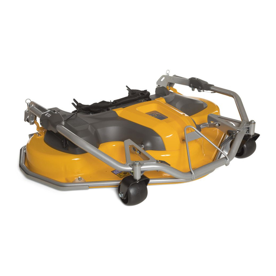
Cutting decks
Hide thumbs
Also See for 110C E QF:
- Operator's manual (312 pages) ,
- Owner's manual (308 pages) ,
- Owner's manual (36 pages)
Table of Contents
Advertisement
Advertisement
Chapters
Table of Contents

Related Manuals for Stiga 110C E QF


Summary of Contents for Stiga 110C E QF
- Page 1 WORKSHOP MANUAL CUTTING DECKS 110C E QF - 125C E QF 2018 - 2020...
- Page 2 All brands, names, logos and trademarks mentioned belong to their respective owners. © by STIGA - No use of the illustrations or duplication, reproduction or translation, even partial, of the texts in this document may be made without explicit authorisation.
- Page 3 WORKSHOP MANUAL Chapter EDITION PAGE Decks 110/125 C E QF 1 - INTRODUCTION 2018 1 - INTRODUCTION Summary HOW TO USE THE GUIDE ................3 1.1.1 Limitation of Responsibility ..............3 1.1.2 Structure of the Manual ................3 1.1.3 Symbols and Definitions used ..............4 WORK SAFETY INSTRUCTIONS ...............
- Page 4 WORKSHOP MANUAL Chapter EDITION PAGE Decks 110/125 C E QF 1 - INTRODUCTION 2018 1.1.3 Symbols and Definitions used a) Symbols They are used to draw the attention of the operator, reminding him to perform the interventions with the necessary attention and caution. Indicates operations that should be carried out with utmost care to avoid impairing the func- tionality and safety of the machine.
- Page 5 WORKSHOP MANUAL Chapter EDITION PAGE Decks 110/125 C E QF 1 - INTRODUCTION 2018 1.2 WORK SAFETY INSTRUCTIONS 1.2.1 Qualification of operators All maintenance, disassembly and repairs must be carried out by expert mechanics who are fa- miliar with all the accident prevention and safety regulations after reading through the procedures in this manual.
- Page 6 WORKSHOP MANUAL Chapter EDITION PAGE Decks 110/125 C E QF 1 - INTRODUCTION 2018 1.3 SERVICE CENTRE PROCEDURES 1.3.1 Equipment registration The Warranty registration card must be completed, signed and returned at the time of purchase. This activates the warranty card. Claims that meet the requirements will be honoured during the limited warranty period.
-
Page 7: Table Of Contents
WORKSHOP MANUAL Chapter EDITION PAGE Decks 110/125 C E QF 2 - INFORMATION FOR SERVICE CENTRES 2018 2 - INFORMATION FOR SERVICE CENTRES Summary GENERAL INFORMATION ................. 7 2.1.1 Equipment identification ................. 7 2.1.2 Safety measures to be adopted .............. 7 2.1.3 Basic equipment.................. -
Page 8: Transportation And Handling
WORKSHOP MANUAL Chapter EDITION PAGE Decks 110/125 C E QF 2 - INFORMATION FOR SERVICE CENTRES 2018 • and also: - restore to proper working order any safety de- vices which have been manipulated or removed; - reassemble inefficient, damaged or missing casings and protection covers;... -
Page 9: Spare Parts
WORKSHOP MANUAL Chapter EDITION PAGE Decks 110/125 C E QF 2 - INFORMATION FOR SERVICE CENTRES 2018 2.2 SPARE PARTS 2.2.1 Non-original spare parts Use original spare parts only. Replacement of any machine component with anything other than a part authorised by the Manufacturer can adversely affect performance, working life or safety of this machine and will void the Warranty. -
Page 10: Characteristics Of The Original Belts
WORKSHOP MANUAL Chapter EDITION PAGE Decks 110/125 C E QF 2 - INFORMATION FOR SERVICE CENTRES 2018 10 / 2.2.3 Characteristics of the original belts The standard belts on the market have different characteristics compared to the requirements of the original spare belts, supplied by the authorised dealer. The latter are designed and manufac- tured in close cooperation with the belt supplier and the machine manufacturer. -
Page 11: Tips For Users
WORKSHOP MANUAL Chapter EDITION PAGE Decks 110/125 C E QF 2 - INFORMATION FOR SERVICE CENTRES 2018 11 / 2.3 TIPS FOR USERS 2.3.1 Cutting height The best cutting results are obtained when cut- ting the upper third of the grass, meaning that 2/3 of the length of the grass remains on the lawn. - Page 12 WORKSHOP MANUAL Chapter EDITION PAGE Decks 110/125 C E QF 3 - ASSEMBLY AND REMOVAL 2018 12 / 3 - ASSEMBLY AND REMOVAL Summary UNPACKING AND COMPLETING THE EQUIPMENT ......12 3.1.1 General information ................12 3.1.2 Assembling the coupling hooks ............12 3.1.3 Basic height adjustment ...............
-
Page 13: Basic Height Adjustment
WORKSHOP MANUAL Chapter EDITION PAGE Decks 110/125 C E QF 3 - ASSEMBLY AND REMOVAL 2018 13 / 3.1.3 Basic height adjustment IMPORTANT This adjustment is ONLY foreseen to check the ratio of the base height of the cutting deck in relation to the diameter of the front wheels of the machine. No exceptions to this equipment design rule are permitted. -
Page 14: Replacing The Belt (For The Park 2Wd Machine Only)
WORKSHOP MANUAL Chapter EDITION PAGE Decks 110/125 C E QF 3 - ASSEMBLY AND REMOVAL 2018 14 / 3.1.4 Replacing the belt (for the Park 2WD machine only) NOTE The equipment is delivered with a belt al- ready assembled and suitable for use on the Park 4WD machine. -
Page 15: Prepare The Machine
Type of machine 110C E QF 125C E QF Notes P 901 C = NOT Applicable... -
Page 16: Installing The Equipment On The Machine
WORKSHOP MANUAL Chapter EDITION PAGE Decks 110/125 C E QF 3 - ASSEMBLY AND REMOVAL 2018 16 / 3.3 INSTALLING THE EQUIPMENT ON THE MACHINE 3.3.1 Coupling and connection of the equipment to the machine Approach and align the equipment in relation to the front of the machine. -
Page 17: Connecting The Belt To The Machine Pto
WORKSHOP MANUAL Chapter EDITION PAGE Decks 110/125 C E QF 3 - ASSEMBLY AND REMOVAL 2018 17 / 6. Position the guard (7) frame (9) in line with the interface bracket (10) and fasten in place with the two screws (11). 7. -
Page 18: Removing The Equipment From The Machine
WORKSHOP MANUAL Chapter EDITION PAGE Decks 110/125 C E QF 3 - ASSEMBLY AND REMOVAL 2018 18 / 3.4 REMOVING THE EQUIPMENT FROM THE MACHINE 3.4.1 Disconnecting and removing equipment from the machine Perform the following procedures in reverse order, as described above: •... - Page 19 WORKSHOP MANUAL Chapter EDITION PAGE Decks 110/125 C E QF 4 - MAINTENANCE 2018 19 / 4 - MAINTENANCE Summary TROUBLESHOOTING ................19 REPLACING OF GUARDS ................ 20 4.2.1 Replacing the belt guard canvas ............20 4.2.2 Replacement of the intermediate guard..........22 REPLACING THE BELTS ................
-
Page 20: Replacing The Belt Guard Canvas
WORKSHOP MANUAL Chapter EDITION PAGE Decks 110/125 C E QF 4 - MAINTENANCE 2018 20 / Problem Probable cause Solution 4. The blade locking • Malfunction of the lock- Replacement of the locking device and device has been trig- ing devices adjustment of the cable 4.4.2] gered with the blades still... - Page 21 WORKSHOP MANUAL Chapter EDITION PAGE Decks 110/125 C E QF 4 - MAINTENANCE 2018 21 / 2. Release the two positioning cables (4) from the lower frame (5) of the belt guard, taking care not to drop them inside the casing under- neath.
-
Page 22: Replacement Of The Intermediate Guard
WORKSHOP MANUAL Chapter EDITION PAGE Decks 110/125 C E QF 4 - MAINTENANCE 2018 22 / 4.2.2 Replacement of the intermediate guard 1. Undo the screw (1) and remove the protection (2) by lifting it from the rear section. 2. Release the two positioning cables (3) from the lower frame (4) of the belt guard. 3. -
Page 23: Replacement Of The Control Belt
WORKSHOP MANUAL Chapter EDITION PAGE Decks 110/125 C E QF 4 - MAINTENANCE 2018 23 / 4.3 REPLACING THE BELTS 4.3.1 Replacement of the control belt NOTE The replacement of the control belt can be performed without having to remove the cutting deck from the machine. - Page 24 WORKSHOP MANUAL Chapter EDITION PAGE Decks 110/125 C E QF 4 - MAINTENANCE 2018 24 / 3. Disconnect the cable (6) from the cable clamp (7) and undo the two screws (8). 4. Remove the upper casing (9), lifting it from the top.
-
Page 25: General Information
WORKSHOP MANUAL Chapter EDITION PAGE Decks 110/125 C E QF 4 - MAINTENANCE 2018 25 / 7. Remove the belt from the central pulley (15), pulling it out between the teeth of the toothed wheel (16) on the locking device. Reassemble the new belt respecting the path in- dicated on the upper casing, following the above procedure in reverse order. -
Page 26: Replacing The Locking Device And Adjusting The Cable
WORKSHOP MANUAL Chapter EDITION PAGE Decks 110/125 C E QF 4 - MAINTENANCE 2018 26 / 4.4.2 Replacing the locking device and adjusting the cable 1. Prepare the cutting deck according to the following procedures • Remove the cutting deck from the machine 3.4.1]. - Page 27 WORKSHOP MANUAL Chapter EDITION PAGE Decks 110/125 C E QF 4 - MAINTENANCE 2018 27 / 6. Remove the cable clamp (10) to allow the ca- ble to be extracted (9). 7. Loosen the adjuster (11), remove the retaining ring (12), extract the pin (13) and remove the cable (9).
-
Page 28: Removing And Reassembling The Blades
WORKSHOP MANUAL Chapter EDITION PAGE Decks 110/125 C E QF 4 - MAINTENANCE 2018 28 / 11. Lower the right arm and adjust the lower adjusting nut (6) to obtain a distance of 24-26 mm between the teeth of the crown (4) and the lock roller (16). 24-26 12. -
Page 29: Sharpening And Balancing The Blades
WORKSHOP MANUAL Chapter EDITION PAGE Decks 110/125 C E QF 4 - MAINTENANCE 2018 29 / WARNING! - Always wear protective gloves when handling the blades. 1. To remove a blade (1), grasp it firmly and undo the central screw (2). To assemble a blade, tighten the screws (2) with a torque wrench set to 47-52 Nm. -
Page 30: Check The Alignment Of The Blade Shafts
WORKSHOP MANUAL Chapter EDITION PAGE Decks 110/125 C E QF 4 - MAINTENANCE 2018 30 / 2. Using the appropriate equipment, check the balance of the blade (1) to make sure that there is a maximum difference of 2 grams between one side and the other. 4.5.3 Check the alignment of the blade shafts NOTE Abnormal vibrations that are not caused by the condition or the balancing of the blades, can cause shaft deformation or excessive play of the support bearings. -
Page 31: Replacement Of The Blade Supports And Shafts
WORKSHOP MANUAL Chapter EDITION PAGE Decks 110/125 C E QF 4 - MAINTENANCE 2018 31 / 4.5.4 Replacement of the blade supports and shafts • Remove the relevant blade 4.5.1]. In case of intervention on the right or left blade support: •... -
Page 32: General Information
WORKSHOP MANUAL Chapter EDITION PAGE Decks 110/125 C E QF 4 - MAINTENANCE 2018 32 / 4.6 REPLACEMENT OF THE UPSTROKE SYNCHRONISATION TIE RODS 4.6.1 General information These tie rods connect the two front and rear axles of the cutting deck upstroke lifting mechanism. If the rods need replacing, it is necessary to respect the distance between the joints. -
Page 33: Replacing The Cable
WORKSHOP MANUAL Chapter EDITION PAGE Decks 110/125 C E QF 4 - MAINTENANCE 2018 33 / 4.7.2 Replacing the cable 1. Remove the crown fastener (1) at the lower end of the handle (3) pin (2) and extract the pin. 2. -
Page 34: Replacement Of The Bushings
WORKSHOP MANUAL Chapter EDITION PAGE Decks 110/125 C E QF 4 - MAINTENANCE 2018 34 / Excessive radial clearance between the wheel support fork and the frame requires the replace- ment of the bushings, which is carried out according to the following procedure. 4.8.2 Replacement of the bushings •... -
Page 35: Routine Maintenance Chart
WORKSHOP MANUAL Chapter EDITION PAGE Decks 110/125 C E QF 4 - MAINTENANCE 2018 35 / 4.9 GENERAL MAINTENANCE 4.9.1 Routine maintenance chart Frequency Operating hours/months Object Related topic First time Next time • Safety measures to be adopted 1. Safety checks 5/–... - Page 36 WORKSHOP MANUAL Chapter EDITION PAGE Decks 110/125 C E QF 4 - MAINTENANCE 2018 36 / 4.9.3 Washing and cleaning Washing the inside of the cutting decks must be carried out with the plate in the "Maintenance / Washing" position, using a water jet cleaner only. IMPORTANT Never use high pressure jets of water.
- Page 37 STIGA S.p.A - Via del Lavoro, 6 - 31033 Castelfranco Veneto (TV) - Italy www.stiga.com...
Need help?
Do you have a question about the 110C E QF and is the answer not in the manual?
Questions and answers