
Related Manuals for BorMann Technik BWR5030


Summary of Contents for BorMann Technik BWR5030
- Page 1 Bwr5030 | ΚΑΜΠΙΝΑ ΑΜΜΟΒΟΛΗΣ 220LT Μετάφραση του πρωτοτύπου των Owner’s manual οδηγιών χρήσης Art Nr: 011286 www.BormannTools.com...
- Page 2 Οδηγίες ασφάλειας • Σιγουρευτείτε ότι τα χαρακτηριστικά της παροχής του μηχανήματος είναι κατάλληλα για την λειτουργία της καμπίνας αμμοβολής. Προσοχή! θα πρέπει να τηρείτε τις παρακάτω οδηγίες για να μειώσετε τον κίνδυνο φωτιάς, ηλεκτροπληξίας και τραυματισμού. • Διαβάστε καλά όλες τις οδηγίες χρήσης και ασφάλειας πριν να επιχειρήσετε να χρησιμοποιήσετε την καμπίνα αμμοβολής. •...
- Page 3 2. Ποτέ μην χρησιμοποιείτε οξυγόνο, διοξείδιο του άνθρακα, εύφλεκτα αέρια ή οποιοδήποτε εμφιαλωμένο αέριο ως πηγή αέρα για το εργαλείο. Τέτοια αέρια είναι ικανά έκρηξης και σοβαρών τραυματισμών για τα άτομα. 3. Ποτέ μην αφήνετε πεπιεσμένο αέρα στο σύστημα παροχής ενώ έχετε τελειώσει με την εργασία. Εκτονώστε τον αέρα από το...
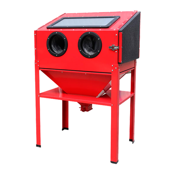
- Page 4 Υποδοχές χειρισμού – ενσωματωμένα γάντια αμμοβολής (41) Μάνταλα σφράγισης πόρτας (12) Θυρίδα απομάκρυνσης σκόνης (22) (στην αριστερή πλευρά της καμπίνας). Πόρτα καμπίνας (13) Αναμονή σύνδεσης σωλήνα (45) Χοάνη (6,7) Στόμιο χοάνης Χειρολαβή (3) Εικόνα Α: Περιγραφή τμημάτων και σημείων ελέγχου Αρχικές...
- Page 5 Εξαρτήματα σύνδεσης Λαμπτήρων Συνδέστε τους σφιγκτήρες (37) στην οπίσθια πλάκα (19) που βρίσκεται στο εσωτερικό της καμπίνας χρησιμοποιώντας τα μπουλόνια που βρίσκονται τοποθετημένα στους σφικτήρες. Εικόνα Β: Σύνδεσμοι σύνδεσης λαμπτήρων Γάντια αμμοβολής 1. Ασφαλίστε τους δακτυλίους στερέωσης γαντιών (33) και τους δακτυλίους στεγανοποίησης των γαντιών (30) στην εμπρόσθια...
- Page 6 Καμπίνα αμμοβολής Σημείωση: Όλες οι φλάντζες είναι προεγκατεστημένες σε όλες τις πλάκες της καμπίνας αμμοβολής. Χρησιμοποίησε ένα ζουμπά ή ένα καρφί για να δημιουργήσετε τρύπες στο στεγνωτικό υλικό για την εγκατάσταση μπουλονιών. Σημείωση: Τοποθετήστε την επάνω πλάκα στην άκρη του τραπεζιού με τις φλάντζες στραμμένες προς τα πάνω. Σημείωση: Ευθυγραμμίστε...
- Page 7 Χοάνη 1. Τοποθετήστε την αριστερή και δεξιά πλάκα της χοάνης (7) στις εσωτερικές φλάντζες της μπροστινής και οπίσθιας πλάκας της χοάνης (6) και ασφαλίστε τες χρησιμοποιώντας τις βίδες(47), τις ροδέλες και τα παξιμάδια. 2. Σύρετε το στόμιο διοχέτευσης (5) πάνω από το κάτω...
- Page 8 Σύνδεση της χοάνης, του σωλήνα και της καμπίνας 1. Τοποθετήστε την κάτω πλάκα (9) η οποία έχει αφρό σε κάθε πλευρά μαζί με το πλαίσιο του παραθύρου(10) στην κορυφή της χοάνης και στερεώστε στο κάτω μέρος της καμπίνας χρησιμοποιώντας τις ροδέλες, τα παξιμάδια και τα μπουλόνια...
- Page 9 2. Συνδέστε έναν εύκαμπτο σωλήνα αέρα στην έξοδο αέρα του συμπιεστή. Συνδέστε τον εύκαμπτο σωλήνα αέρα στην είσοδο αέρα του εργαλείου. Εξαρτήματα, όπως είναι ένα σετ μαστού και ταχυσύνδεσμος, θα καταστήσουν την λειτουργία πιο αποτελεσματική, αλλά δεν είναι απαραίτητα. Προσοχή! Για την αποφυγή τραυματισμού λόγω ακούσιας εκκίνησης: Μην...
- Page 10 Τεμάχιο κατεργασίας και διαμόρφωση χώρου εργασίας 1. Επιλέξτε ένα χώρο εργασίας που είναι καθαρός και καλά φωτιζόμενος. 2. Περάστε τον εύκαμπτο σωλήνα αέρα κατά μήκος μιας ασφαλούς διαδρομής προς την περιοχή εργασίας με τέτοιον τρόπο ώστε να μην δημιουργεί κίνδυνο ανατροπής του χειριστή και να μην είναι εκτεθειμένος για την αποφυγή βλάβης. Ο...
- Page 11 εξωτερικές επιφάνειες του εργαλείου με ένα καθαρό, στεγνό πανί. Στη συνέχεια αποθηκεύστε το εργαλείο σε εσωτερικό χώρο μακριά από τα παιδιά. Οδηγίες συντήρησης Οι διαδικασίες που δεν εξηγούνται ειδικά στο παρόν εγχειρίδιο πρέπει να εκτελούνται μόνο από εξειδικευμένο τεχνικό. Ακούσια εκκίνηση: Απενεργοποιήστε...
- Page 12 INSTRUCTIONS PERTAINING TO A RISK OF FIRE, ELECTRIC SHOCK, OR INJURY TO PERSONS WARNING – When using tools, basic precautions should always be followed, including the following: General To reduce the risks of electric shock, fire, and injury to persons, read all the instructions before using the tool. Work Area Keep the work area clean and well lighted.
- Page 13 Service 1. Tool service must be performed only by qualified repair personnel. 2. When servicing a tool, use only identical replacement parts. Use only authorized parts. Air Source Never connect to an air source that is capable of exceeding 200 psi. Over pressurizing the tool may cause bursting, abnormal operation, breakage of the tool or serious injury to persons.
- Page 14 Vibration Precautions This tool vibrates during use. Repeated or long-term exposure to vibration may cause temporary or permanent physical injury, particularly to the hands, arms and shoulders. To reduce the risk of vibration-related injury: 1. Anyone using vibrating tools regularly or for an extended period should first be examined by a doctor and then have regular medical check-ups to ensure medical problems are not being caused or worsened from use.
- Page 15 Initial Tool Set up / Assembly Read the ENTIRE IMPORTANT SAFETY INFORMATION section at the beginning of this manual including all text under subheadings therein before set up or use of this product. Note: For additional information regarding the parts listed in the following pages, refer to the Assembly Diagram near the end of this manual Light Clamps Attach the Light Clamps (37) to the inside of the Cabinet Rear Plate (19) using the bolts which are pre-assembled on the Light...
- Page 16 Cabinet Note: All gaskets are pre-fitted on all needed plates. Use a punch or nail to make holes in the Foam Gasket for bolt installation. TOP TIP: Place the top plate on a table edge with the gaskets facing up. Note: Align the three middle holes along the Top Plate (16) first, then align the remaining holes when assembling.
- Page 17 Funnel 1. Place the Funnel Left and Right Plates (7) on the inside flanges of the Funnel Front and Rear Plates (6) and secure in place with the Bolts (47), Flat Washers and Nuts. 2. Slide the Funnel Mouth (5) over the bottom of the assembly and secure in place with the Bolts, Flat Washers and Nuts pre- assembled on the Funnel Mouth.
- Page 18 Connecting the Funnel, Hose and Cabinet 1.Place the Bottom Plate (9) which has foam on each side together with Screen Frame (10) on top of the Funnel and secure the assembly to the bottom of the Cabinet with the Bolts (44) Flat Washers and Nuts.
- Page 19 Note: An oiler system should not be used with this tool. The oil will mix with the material being propelled, causing tool to clog. 2. Attach an air hose to the compressor's air outlet. Connect the air hose to the air inlet of the tool. Other components, such as a coupler plug and quick coupler, will make operation more efficient, but are not required.
- Page 20 General Operating Instructions 1. Connect the air compressor hose to the Hose Inlet Fitting. 2. Turn on the vacuum of the dust collection system (if equipped, sold separately). Note: When using a vacuum dust collector, clean the filter periodically to maintain adequate suction and effectiveness of the vacuum.
- Page 21 Operating Instructions Read the ENTIRE IMPORTANT SAFETY INFORMATION section at the beginning of this manual including all text under subheadings therein before set up or use of this product. Inspect tool before use, looking for damaged, loose, and missing parts. If any problems are found, do not use tool until repaired.
- Page 22 b. Turn off the compressor and dust collection system (if equipped). Wait for the air inside the Cabinet to clear. c. Open the Cabinet door and remove the workpiece. If the workpiece needs more blasting, resume from step 4 of these operating instructions.
-
Page 23: Troubleshooting
Troubleshooting Problem Possible Causes Likely Solutions Decreased output. 1. Not enough air pressure and/ 1. Check for loose connections and make sure that or air flow. air supply is providing enough air flow (l/min) at required pressure (bar) to the tool's air inlet. Do not exceed maximum air pressure. -
Page 24: Please Read The Following Carefully
Parts List and Diagram PLEASE READ THE FOLLOWING CAREFULLY THE MANUFACTURER AND/OR DISTRIBUTOR HAS PROVIDED THE PARTS LIST AND ASSEMBLY DIAGRAM IN THIS MANUAL AS A REFERENCE TOOL ONLY. NEITHER THE MANUFACTURER OR DISTRIBUTOR MAKES ANY REPRESENTATION OR WARRANTY OF ANY KIND TO THE BUYER THAT HE OR SHE IS QUALIFIED TO MAKE ANY REPAIRS TO THE PRODUCT, OR THAT HE OR SHE IS QUALIFIED TO REPLACE ANY PARTS OF THE PRODUCT. -
Page 25: Assembly Diagram
Assembly Diagram...
Need help?
Do you have a question about the Technik BWR5030 and is the answer not in the manual?
Questions and answers