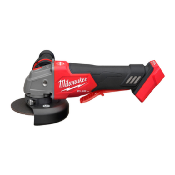
Summary of Contents for Milwaukee M18 FAG125XPD
- Page 1 OPERATOR'S MANUAL Cat. No. M18 FAG125XPD M18 FUEL™ 125 MM (5") ANGLE GRINDER WITH DEADMAN PADDLE SWITCH WARNING To reduce the risk of injury, user must read and understand operator's manual.
-
Page 2: Electrical Safety
GENERAL POWER TOOL • Remove any adjusting key or wrench before turning the power tool on. A wrench or a key left SAFETY WARNINGS attached to a rotating part of the power tool may result Read all safety warnings, instruc- WARNING in personal injury. - Page 3 • When battery pack is not in use, keep it away • Do not use a damaged accessory. Before each from other metal objects, like paper clips, coins, use inspect the accessory such as abrasive keys, nails, screws or other small metal objects, wheels for chips and cracks, backing pad for that can make a connection from one terminal to cracks, tear or excess wear, wire brush for loose...
- Page 4 Maintain labels and nameplates. These carry pressure. Do not attempt to make an excessive important information. If unreadable or missing, depth of cut. Overstressing the wheel increases contact a MILWAUKEE service facility for a ® the loading and susceptibility to twisting or binding replacement.
-
Page 5: Functional Description
• lead from lead-based paint SPECIFICATIONS • crystalline silica from bricks and cement and other Cat. No........M18 FAG125XPD masonry products, and Volts .............18V DC • arsenic and chromium from chemically-treated lumber. Battery Type ..........M18™ Your risk from these exposures varies, depending on Charger Type ..........M18™... - Page 6 Inspect the parts for damage. tool. Hold securely. Replace if needed. Use only MILWAUKEE ® mounting hardware designed for your tool. 4. Place the flange on spindle, as shown. Installing Side Handle The side handle may be installed on either side of Flange nut the gear case.
-
Page 7: Operation
Replace needed. only Always hold tool with WARNING MILWAUKEE mounting hardware designed for ® th hand sing the hand your tool. provided before and during grinding. 3. Slip backing pad onto spindle with flat side away from gear case. - Page 8 Paddle Switch Operation using only the edge of the wheel. To start the tool, grasp the handle and side handle Using the face of a Cut-Off Wheel WARNING the paddle switch. (as in grinding) will cause the To stop the tool, release the paddle switch. Make Wheel to crack and break, resulting in serious sure the tool comes to a complete stop before laying personal injury.
-
Page 9: Troubleshooting
15 angle to ensure proper sanding tool operation. Return the tool, battery pack, and pressure and control. Too great an angle will result charger to a MILWAUKEE service facility for repair. ® in too much pressure and could cause excessive After six months to one year, depending on use, wear to the disc and workpiece. - Page 12 Australia and New Zealand. SERVICE - AUSTRALIA and NEW ZEALAND MILWAUKEE ® prides itself in producing a premium quality product that is Nothing But Heavy Duty Your satisfaction with our products is very important to us! If you encounter any problems with the operation of this tool, please contact your authorised MILWAUKEE ®...


Need help?
Do you have a question about the M18 FAG125XPD and is the answer not in the manual?
Questions and answers