
Related Manuals for Daikin FXZA15A2VEB


Summary of Contents for Daikin FXZA15A2VEB
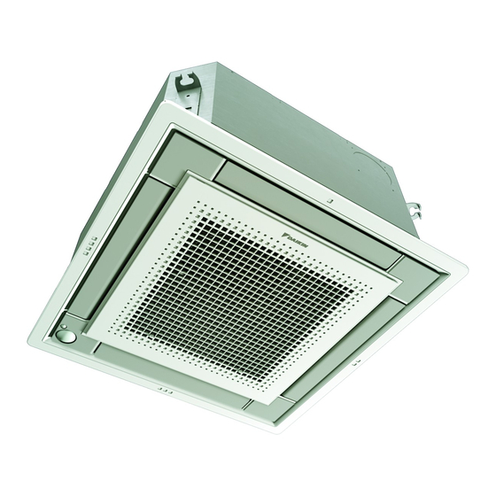
- Page 1 Installation and operation manual VRV system air conditioner FXZA15A2VEB FXZA20A2VEB FXZA25A2VEB FXZA32A2VEB Installation and operation manual FXZA40A2VEB English VRV system air conditioner FXZA50A2VEB...
- Page 2 3P480520-16E...
-
Page 3: Table Of Contents
▪ A subset of the latest technical data is available on the regional 13 Piping installation Daikin website (publicly accessible). 13.1 Preparing refrigerant piping............16 ▪ The full set of latest technical data is available on the Daikin 13.1.1 Refrigerant piping requirements........16 Business Portal (authentication required). 13.1.2 Refrigerant piping insulation ........ -
Page 4: Instructions For Equipment Using R32 Refrigerant
WARNING Make sure installation, servicing, maintenance, repair and ▪ If the power supply has a missing or wrong N-phase, applied materials follow the instructions from Daikin and, in equipment might break down. addition, comply with applicable legislation and are ▪ Establish proper earthing. Do NOT earth the unit to a performed by qualified persons only. -
Page 5: Installation Space Requirements
WARNING Make sure installation, servicing, maintenance and repair CAUTION comply with instructions from Daikin and with applicable Do NOT use potential sources of ignition in searching for legislation (for example national gas regulation) and are or detection of refrigerant leaks. -
Page 6: Instructions For Safe Operation
3 User safety instructions given supervision or instruction Instructions for safe operation concerning the use of the appliance by WARNING a person responsible for their safety. ▪ Do NOT modify, disassemble, Children MUST NOT play with the remove, reinstall or repair the unit appliance. - Page 7 3 User safety instructions CAUTION WARNING To avoid oxygen deficiency, ventilate NEVER replace a fuse with a fuse of a the room sufficiently if equipment with wrong ampere ratings or other wires burner is used together with the when a fuse blows out. Use of wire or system.
-
Page 8: About The System
4 About the system ▪ Be aware that the refrigerant inside About the system the system is odourless. WARNING WARNING ▪ Do NOT modify, disassemble, remove, reinstall or repair the unit yourself as incorrect dismantling or The refrigerant inside the unit is mildly installation may cause an electric shock or fire. -
Page 9: User Interface
5 User interface Icon Operation mode User interface Fan only. In this mode, air circulates without heating or cooling. CAUTION ▪ NEVER touch the internal parts of the controller. Dry. In this mode, the air humidity will be lowered with a minimal temperature decrease. -
Page 10: To Operate The System
7 Maintenance and service INFORMATION CAUTION Depending on system layout and organisation, Auto airflow After a long use, check the unit stand and fitting for direction may not be available. damage. If damaged, the unit may fall and result in injury. INFORMATION NOTICE For setting procedure of the airflow direction, see the... -
Page 11: To Clean The Suction Grille
7 Maintenance and service 2 Remove the air filter. BYFQ60C BYFQ60B BYFQ60C 90° 3 Remove the air filter. BYFQ60B BYFQ60C 3 Clean the air filter. Use a vacuum cleaner or wash with water. If the air filter is very dirty, use a soft brush and neutral detergent. 4 Dry the air filter in the shadow. -
Page 12: About The Refrigerant Leakage Sensor
8 Troubleshooting In case of detection when the unit is standby NOTICE When the detection occurs when the unit is standby, "false detection Applicable legislation on fluorinated greenhouse gases check" will occur. requires that the refrigerant charge of the unit is indicated both in weight and CO equivalent. -
Page 13: Relocation
9 Relocation INFORMATION Disposal Refer reference guide located http:// www.daikineurope.com/support-and-manuals/product- NOTICE information/ for more troubleshooting tips. Do NOT try to dismantle the system yourself: dismantling of the system, treatment of the refrigerant, oil and other If after checking all above items, it is impossible to fix the problem parts MUST comply with applicable legislation. -
Page 14: Mounting The Indoor Unit
12 Unit installation ▪ Install inspection opening on the control box side to make ▪ Suspension bolts. Use M8~M10 suspension bolts for installation. maintenance easier. Attach the hanger bracket to the suspension bolt. Fix it securely using a nut and washer from the upper and lower sides of the hanger bracket. -
Page 15: Guidelines When Installing The Drain Piping
12 Unit installation ▪ Rising piping. If necessary to make the slope possible, you can Example If A Then install rising piping. ▪ Drain hose inclination: 0~75 mm to avoid stress on the piping BYFQ60B and to avoid air bubbles. 585 mm 5 mm 57.5 mm... -
Page 16: Piping Installation
13 Piping installation Metal clamp (accessory) 6 Disconnect the electrical wiring. Large sealing pad (accessory) ▪ Remove the service cover. Drain piping (field supply) ▪ Disconnect the power supply. To check for water leaks ▪ Disconnect the user interface. ▪ Reattach the service cover. The procedure differs depending on whether installation of the system is already completed. -
Page 17: Connecting The Refrigerant Piping
14 Electrical installation Pipe outer diameter Insulation inner Insulation thickness Electrical installation (Ø diameter (Ø 6.4 mm (1/4") 8~10 mm ≥10 mm DANGER: RISK OF ELECTROCUTION 9.5 mm (3/8") 12~15 mm ≥13 mm WARNING 12.7 mm (1/2") 14~16 mm ≥13 mm ALWAYS use multicore cable for power supply cables. Ø... -
Page 18: Commissioning
15 Commissioning 3 Transmission cable: Route the cable through the frame, CAUTION connect the cable to the terminal block (make sure the symbols ▪ Each indoor unit has to be connected to a separate F1, F2 match with the symbols on the outdoor unit), and fix the user interface. -
Page 19: To Perform A Test Run
16 Configuration 15.2 To perform a test run If the distance to the floor is (m) Then — INFORMATION ≤2.7 13 (23) ▪ Perform the test run according to the instructions in the 2.7<x≤3.0 outdoor unit manual. 3.0<x≤3.5 ▪ The test run is only completed if there is no malfunction Setting: Airflow direction range code displayed on the user interface or the outdoor unit 7‑segment display. -
Page 20: Technical Data
▪ A subset of the latest technical data is available on the regional Connector (frame ground) Daikin website (publicly accessible). Harness ▪ The full set of latest technical data is available on the Daikin Business Portal (authentication required). H*P, LED*, V*L Pilot lamp, light emitting diode... - Page 21 17 Technical data Symbol Meaning Symbol Meaning Intelligent eye sensor Ferrite core IPM* Intelligent power module ZF, Z*F Noise filter K*R, KCR, KFR, KHuR, K*M Magnetic relay Live Coil Reactor Stepper motor Compressor motor Fan motor Drain pump motor Swing motor MR*, MRCW*, MRM*, MRN* Magnetic relay Neutral...
- Page 24 3P599603-1C 2020.10 Verantwortung für Energie und Umwelt...
Need help?
Do you have a question about the FXZA15A2VEB and is the answer not in the manual?
Questions and answers