Table of Contents
Advertisement
SYSTEM Inverter Air Conditioners
MODELS
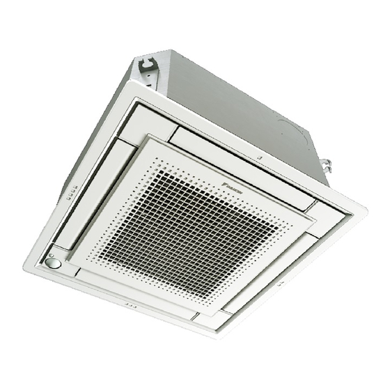
Ceiling Mounted Cassette type (Multi Flow)
FXZQ05TAVJU
FXZQ07TAVJU
FXZQ09TAVJU
FXZQ12TAVJU
FXZQ15TAVJU
FXZQ18TAVJU
Read these instructions carefully before installation.
Keep this manual in a handy place for future reference.
This manual should be left with the equipment owner.
Lire soigneusement ces instructions avant l'installation.
Conserver ce manuel à portée de main pour référence ultérieure.
Ce manuel doit être donné au propriétaire de l'équipement.
Lea cuidadosamente estas instrucciones antes de instalar.
Guarde este manual en un lugar a mano para leer en caso de tener alguna duda.
Este manual debe permanecer con el propietario del equipo.
INSTALLATION MANUAL
English
Français
Español
Advertisement
Table of Contents

Related Manuals for Daikin FXZQ05TAVJU


Summary of Contents for Daikin FXZQ05TAVJU
-
Page 1: Installation Manual
INSTALLATION MANUAL SYSTEM Inverter Air Conditioners MODELS Ceiling Mounted Cassette type (Multi Flow) FXZQ05TAVJU FXZQ07TAVJU English FXZQ09TAVJU FXZQ12TAVJU FXZQ15TAVJU Français FXZQ18TAVJU Read these instructions carefully before installation. Español Keep this manual in a handy place for future reference. This manual should be left with the equipment owner. - Page 2 ≥60* ≥60* (≥1500*) (≥1500*) ≥60 × (≥1500) : Blocking pad kit Unit: in. (mm) 21 (533) 21 (533) 22-5/8 (575) 22-5/8 (575) 2-1/2 2-1/2 (63) (63) 23-1/16-26 (585-660) 23-1/16-23-7/16 (585-595) 24-7/16 (620) 27-9/16 (700) 23-1/16-23-7/16 (585-595) 23-1/16-26 (585-660) ≥ * 1/2 ≥...
- Page 3 Control box IN/D OUT/D Unit: in. (mm) Control box IN/D OUT/D Control box Control box IN/D OUT/D OUT/D IN/D...
- Page 4 • If refrigerant gas leaks during installation, ventilate tion device is shorted and operated forcibly, or parts the area immediately. Refrigerant gas may produce other than those specified by Daikin are used, fire or toxic gas if it comes in contact with fire. Exposure to explosion may occur. this gas could cause severe injury or death.
- Page 5 (b) Where corrosive gas, such as sulfurous acid gas, CAUTION is produced. • Do not touch the switch with wet fingers. Touching a Corroding copper pipes or soldered parts may switch with wet fingers can cause electric shock. result in refrigerant leakage. • Do not allow children to play on or around the unit to (c) Near machinery emitting electromagnetic waves. prevent injury.
-
Page 6: Table Of Contents
IMPROPER INSTALLATION OR ATTACHMENT OF EQUIPMENT OR ACCESSORIES COULD RESULT IN ELECTRIC SHOCK, SHORT-CIRCUIT, LEAKS, FIRE OR OTHER DAMAGE TO THE EQUIPMENT. BE SURE ONLY TO USE ACCESSORIES MADE BY DAIKIN WHICH ARE 1 pc. 1 pc. 1 pc. 1 pc. -
Page 7: Selecting Installation Site
Optional accessories a Indoor unit b Lighting „ There are two types of remote controllers: wired and wireless. The figure describes a surface mounted light, but a recessed Select a remote controller according to customer’s request and ceiling light is not restricted. install in an appropriate place. -
Page 8: Preparations Before Installation
4 Use suspension bolts for installation. Check whether the ceiling is 3 Install the suspension bolts. strong enough to support the weight of the indoor unit. If there is a (Use either a M8-M10 size bolt or equivalent.) risk, reinforce the ceiling before installing the unit. Use anchors for existing ceilings, and a sunken insert, sunken (The installation pitch is marked on the paper pattern for installation. -
Page 9: Refrigerant Piping Work
3 Adjust the unit to the right position for installation. „ When connecting the fl are nut, coat the fl are inner surface with (See “Preparations before installation” on page 3.) ether oil or ester oil and initially tighten 3 or 4 turns by hand before tightening fi rmly. -
Page 10: Drain Piping Work
Cautions for brazing - After the testing of drain piping is fi nished, attach the drain sealing pad (4) supplied with the unit over the uncovered part of „ Be sure to carry out a nitrogen blow when brazing. the drain socket (= between drain hose and unit body). Brazing without carrying out nitrogen replacement or releasing nitrogen into the piping will create large quantities of oxidized fi lm A-A'... -
Page 11: Electric Wiring Work
Electric wiring work The incline of attached drain hose should be NOTE 3 in. (75 mm) or less so that the drain socket does not have to withstand additional force. General instructions To ensure a downward slope of 1:100, install hanging bars every 39-1/2 in. -
Page 12: Wiring Example And How To Set The Remote Controller
Electrical characteristics controller Indoor units Power supply Fan motor Voltage Model Volts range Connection of power supply, transmission and remote controller wiring FXZQ05TAVJU 0.05 FXZQ07TAVJU 0.05 How to connect wiring (See figure 9) FXZQ09TAVJU 0.05 208- MAX.253 (1) Remove the control box lid (2 screws). MIN.187 FXZQ12TAVJU 0.05... -
Page 13: Wiring Example
Wiring example Precautions 1 Observe the notes mentioned below when wiring to the power Fit the power supply wiring of each unit with a switch and fuse as supply terminal block. shown in figure 16. - Use a round crimp-style terminal for insulation sleeve for connection to the terminal block for wiring the units. - Page 14 Summary of field settings Output signal X1- Thermostat-on + X2 of the optional — Operation Malfunction compressor run KRP1B PCB kit Second code No. (Note 2) Mode First ON/OFF input from outside code Description of setting (T1/T2 input) = Setting ON/OFF Forced OFF —...
-
Page 15: Test Operation
For Control with 2 Remote Controllers (To control 1 indoor For remote control (force off or on / off operation) unit with 2 remote controllers) 1 Wiring method and specification • For control with 2 remote controllers, set one remote controller as • Remote control is available by connecting the external input to Main and the other remote controller as Sub. - Page 16 3P493125-1 EM17A018 [1709]...
Need help?
Do you have a question about the FXZQ05TAVJU and is the answer not in the manual?
Questions and answers