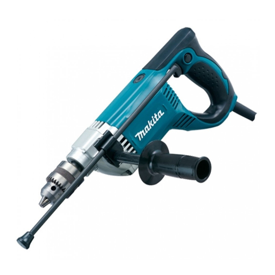
Makita 6305 Technical Information
Hide thumbs
Also See for 6305:
- Instruction manual (45 pages) ,
- Specifications (2 pages) ,
- Instruction manual (9 pages)
Advertisement
Quick Links
T
ECHNICAL INFORMATION
Models No.
Description
C
ONCEPT AND MAIN APPLICATIONS
Model 6305 features;
*Rear handle with soft rubber grip, ergonomically designed
for comfortable operation
*Warning lamp that indicates trouble with the cord, the switch
or the motor
S
pecification
Voltage (V)
110
120
220
230
240
Capacities: mm (")
No load speed: min-
Chuck capacity: mm (")
Double insulation
Power supply cord: m (ft)
Net weight: kg (lbs)
S
tandard equipment
Chuck key S13 ............ 1
Depth gauge ................ 1
Key holder 12 .............. 1
Grip 36 complete ......... 1
Note: The standard equipment for the tool shown above may differ by country.
O
ptional accessories
Drills bits (for metal) 1.5, 2, 3, 4, 5, 6
Auger bits 9, 12, 15
Grip 36 assembly
6305
Drill 13mm (1/2")
Cycle (Hz)
Current (A)
4.1
50/ 60
3.9
50/ 60
Steel
Wood
=rpm.
1
2 - 13mm (1/16 - 1/2)
Australia, New Zealand: 2.0 (6.8)
Other countries: 2.5 (8.2)
Continuous Rating (W)
Input
850
850
13 (1/2)
30 (1-3/16)
1,300
Yes
Europe: 2.5 (8.2)
2.6 (5.7)
PRODUCT
L
W
Dimensions: mm (")
Length (L)
346 (13-5/8)
Width (W)
84 (3-5/16)
Height (H)
Max. Output (W)
Output
450
750
450
750
P 1 / 8
H
152 (6)
Advertisement

Related Manuals for Makita 6305


Summary of Contents for Makita 6305
- Page 1 Models No. 6305 Description Drill 13mm (1/2") ONCEPT AND MAIN APPLICATIONS Model 6305 features; *Rear handle with soft rubber grip, ergonomically designed for comfortable operation *Warning lamp that indicates trouble with the cord, the switch or the motor Dimensions: mm (")
-
Page 2: Necessary Repairing Tools
Removing Bearing retainer 718024-2 Wrench 43 Removing broken Drill chuck [2] LUBRICATION Put approx. 9g of Makita grease N No.1 in the gear room of Gear housing to protect parts and product from unusual abrasion. [3] DISASSEMBLY/ASSEMBLY [3] -1. Drill Chuck DISASSEMBLING 1) Fix Drill chuck extractor (No.1R139) in vise, and fix Hex bar with 12.7mm square shaft (No.1R298) securely in... - Page 3 P 3 / 8 epair [3] -2. Spindle and Gear Section DISASSEMBLING 1) Remove Drill chuck as described in [3] -1. 2) Remove Carbon brush, and unscrew four 5x40 Tapping screws that fasten Gear housing to Motor housing. 3) Separate Gear housing from Gear housing cover complete. Use of Grip complete will make the removal easier. Attach Grip complete to gear housing, and tap the shaft portion with a plastic hammer.
- Page 4 P 4 / 8 epair [3] -3. Armature DISASSEMBLING 1) Remove Drill chuck as described in [3] -1. 2) Remove Carbon brush, and unscrew four 5x40 Tapping screws that fasten Gear housing to Motor housing. 3) Separate Gear housing from Gear housing cover complete. (Fig. 4) 4) From Motor housing, separate Gear housing cover complete together with Armature.
- Page 5 P 5 / 8 High Voltage Countries and Areas where Noise Suppression is Required by Regulation ircuit diagram Fig. 13 Color index of lead wires' sheath Orange Black Clear White Insulated connecter Noise Heat-shrink tube Earth terminal suppressor Switch Support complete Choke coil Warning lamp...
- Page 6 P 6 / 8 High Voltage Countries and Areas where Noise Suppression is Required by Regulation iring diagram [2] Motor Housing Put Earth terminal in place as illustrated in Fig. 15. Fig. 15 Earth terminal Polyolefin tube Motor housing viewed from Lead Wire (clear) Earth terminal Noise suppressor...
-
Page 7: Motor Housing
P 7 / 8 High Voltage Countries and Areas where Noise Suppression is Not Required ircuit diagram Fig. 17 Color index of lead wires' sheath Black Blue White Clear Insulated connecter Noise Heat-shrink tube Earth terminal suppressor* Switch Support complete Line filter** Warning lamp Blue or White... - Page 8 P 8 / 8 High Voltage Countries and Areas where Noise Suppression is Not Required iring diagram [3] Handle Portion of Motor Housing Fig. 19 Be careful not to route the lead wires (black) Fix lead wire (clear) of Noise suppressor of Noise suppressor over the ribs.
Need help?
Do you have a question about the 6305 and is the answer not in the manual?
Questions and answers