Table of Contents
Advertisement
Quick Links
Advertisement
Table of Contents

Related Manuals for Infinite AERINOS ADS-260


Summary of Contents for Infinite AERINOS ADS-260
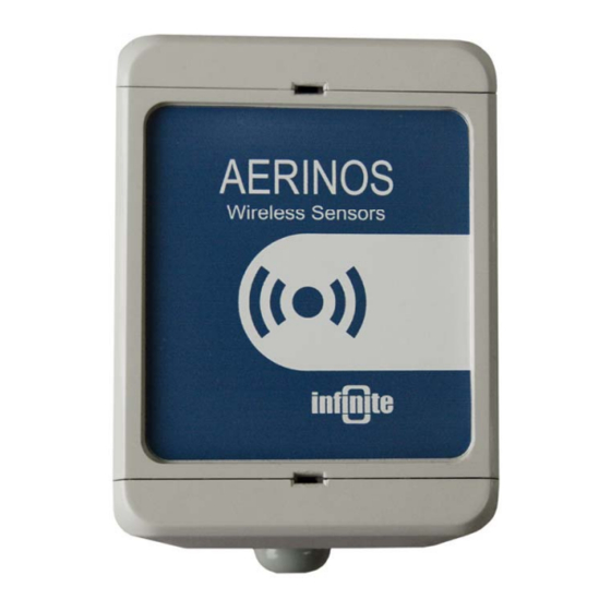
- Page 1 AERINOS ® Sigfox IoT Platform ADS-260 End Node User Guide...
- Page 2 While every effort has been made to ensure that the information in this guide is accuRate and complete, no liability can be accepted for any errors or omissions. Infinite Ltd reserves the right to change the specifications of the hardware and software described in this guide at any time without prior notice.
-
Page 3: Table Of Contents
Contents 1. Introduction 2. Operation modes 3. Hardware setup 3.1 Packing list 3.2 Opening the enclosure 3.3 Connectors & Jumper settings 3.4 Battery installation 3.5 Wiring the digital (Counter) Input 3.6 Wiring the analog input 3.7 Wiring the SDI-12 Serial Bus 3.8 Wiring the RS-485 Bus 4. -
Page 4: Introduction
1. Introduction Sigfox is a communication protocol that is used to read data from sensors through a fixed network of base stations. It works like a low cost “SMS” service. As an end-user, you only need to buy a subscription to connect to the data network operated by SIGFOX. -
Page 5: Operation Modes
2. Operation modes Modes of operation include: 1. Battery supplied cyclic operation. 2. External power adaptor supplied cyclic operation. The transition between the two operation modes is uninterruptible. 3. Operation suspension for the device configuration. 3. Hardware setup 3.1 Packing list 1. -
Page 6: Connectors & Jumper Settings
3.3 Connectors & Jumper settings 3.3.1 LED D13: Status LED, Blinking in configuration mode. 3.3.2 Connectors JMP1: Put a Jumper to enter configuration mode. J2: USB Serial connector. The unit can be supplied through the USB connector for configuration and test. Caution: Remove the external power supply (J5-1), if applied, before connecting the USB connector! J4: Battery connector. -
Page 7: Battery Installation
3.4 Battery installation WARNING: Pay attention to the correct polarity during battery installation! The right polarity is marked up on the Battery Holder. The unit is protected against reverse polarity. 3.5 Wiring the digital (Counter) Input COM: GND Digital Input states are: Contact closed ... -
Page 8: Wiring The Analog Input
3.6 Wiring the analog input ADS-260 incorporates 1 analog input with 12 bit resolution. The Analog input is scanned according to the selected message transmission period (see 4.5.2). For current measurements, an external 47R/0.25W resistor can be applied between the input terminals (J6-1 and J6-5) on IN1. ADU-260 incorporates two excitation outputs (12V, 5V) to supply external transducers. - Page 9 3.6.3 AD592 temperature transducer (-25°C … 105°C) Scale settings: -25°C … 105°C Sensor Output: 0.641V..0.977V, Raw scale: 2625..4001 3.6.4 TMP36 temperature transducer (-40°C … 50°C) Scale settings: -40°C … 50°C Sensor Output: 0.1V..1V, Raw scale: 410..4095 ADS-260 User Guide...
-
Page 10: Wiring The Sdi-12 Serial Bus
3.7 Wiring the SDI-12 Serial Bus SDI-12 is an asynchronous, ASCII, serial communications protocol that was developed for intelligent sensory instruments that typically monitor environmental data. The communication is achieved by digital communications. The addressing system allows data recorder to communicate with several microprocessor-based sensors over a single line. -
Page 11: Device Configuration
4. Device configuration 4.1 Configuring IN1 as Counter input The command enables counting mode on IN1. The Counter (0-65535) is cleared according to a Clear Mode parameter, thereby acting as a Totalizer or a virtual Analog Channel. 1150,n 1150: Command ID 1, CNT number 4.1.1 Counter Scale factor 1154,n,f... -
Page 12: Configuring In1 As Analog Input
4.2 Configuring IN1 as Analog Input The AI configuration command structure is: 1200,n,ssl,ssh,sl,sh 1200: Command ID 1, AI number ssl: Sensor scale low (Row value 0-4095) ssh: Sensor scale high (Row value 0-4095) User scale low User scale high 4.2.1 Clear AI Configuration 1210,n 1210: Command ID... - Page 13 aD0! (aD1!...aD9!) The addressed sensor responds with: a<values><CR><LF> where, <values> - pd.d p - the polarity sign (+ or -) d - numeric digits before the decimal place . - the decimal point (optional) d - numeric digits after the decimal point. the maximum number of digits for a data value is 7, even without a decimal point, the minimum number of digits for a data value (excluding the decimal point) is 1, the maximum number of characters in a data value is 9 (the (polarity sign + 7 digits + the decimal point))
-
Page 14: Configuring The Modbus (Rs-485) Channels
4.4 Configuring the MODBUS (RS-485) channels ADU-500 supports up to 8 MODBUS channels. The configuration command for a MODBUS channel is: 1241,n,a,c,sr,nr 1241: Command ID Channel number (1-8) RS-485 address MODBUS command Start register Number of registers 4.4.1 Start Measurement Trigger command The command concerns sensors requiring a trigger to make a measurement. -
Page 15: Data Acquisition Parameters
4.5 Data Acquisition Parameters 4.5.1 Sampling delay (Warm up time) The parameter defines an idle period between switching on the excitation and reading the measurements from the analog and the SDI-12 channels. This option should be set according to the transducer with the longest warm up time for stable reading. value of this parameter affects strongly the battery life. -
Page 16: Programming The Unit
5. Programming the unit The way to enter the unit setup mode is the following: 1. Install the USB driver on a PC. 2. Connect the USB port to a PC. The Status LED is lighting for 2 sec. 3. Put a Jumper on JMP1. The Status LED starts blinking, indicating setup mode. Program execution is suspended. -
Page 17: Technical Characteristics
6. Technical characteristics Power supply Internal 3.6V Ah Lithium Thionyl battery External 5VDC stabilized power adaptor USB interface (Configuration) Temperature Operation -40 to 65 ºC Storage -45 to 85 ºC Current draw Standby 18 uA max Measurement 6.5 mA (w/o sensor current) 865-870MHz Band (ETSI): 58mA Messaging 902-928 MHz Band (FCC): 292mA... -
Page 18: Command Summary
7. Command Summary 7.1 Configuration Commands Description Syntax Comments 0160 Clear Event Log 0183 Set Factory Defaults cmd,cmd 0205 Reset Unit Operation cmd,cmd 0301 Set Device ID cmd,id,p id: unit ID, p: password 0790 Show Status Messages 0791 Hide Status Messages 1150 Enable Counter cmd,n... -
Page 19: Verification Commands
7.2 Verification Commands Description Syntax Comments 2000 Get Device Status Get Event Log Entries 2160 Number 2161 Get Event Log Last Entries cmd,n n: event log entries (0: all) 2301 Get Device ID 3160 Get Counter Settings cmd,n n: counter 3210 Get AI Settings cmd,n... -
Page 20: References
8. References SDI-12, A Serial-Digital Interface Standard for Microprocessor-Based Sensors Version 1.3. January 3, 2012 SDI-12 Support Group (Technical Committee), 165 East 500 South, River Heights, Utah, 435-752-4200, 435-752-1691 (FAX), http://www.sdi-12.org ADS-260 User Guide...
Need help?
Do you have a question about the AERINOS ADS-260 and is the answer not in the manual?
Questions and answers