
Related Manuals for Eglo Casou


Summary of Contents for Eglo Casou
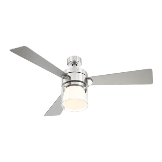
- Page 1 • CEILING FAN OWNER'S MANUAL • Read and Save These Instructions • Casou • 203215A 203217A...
-
Page 2: Tools And Materials Required
TOOLS AND MATERIALS REQUIRED Philips screw driver Blade screw driver 11 mm wrench Step ladder Wire cutters PACKAGE CONTENTS Unpack your fan and check the contents. You should have the following items: a. Blade set (3) b. Hanger bracket assembly c. -
Page 3: Safety Rules
SAFETY RULES 1. To reduce the risk of electric shock, insure 8. Avoid placing objects in the path of the blades. electricity has been turned off at the circuit 9. To avoid personal injury or damage to the fan breaker or fuse box before beginning. and other items, be cautious when working around or cleaning the fan. -
Page 4: Mounting Options
MOUNTING OPTIONS If there isn't an existing UL/CUL listed mounting box, then read the following instructions. Disconnect the power by removing fuses or turning off circuit breakers. Secure the outlet box directly to the building structure. Use appropriate fasteners and building materials. -
Page 5: Hanging The Fan
HANGING THE FAN REMEMBER: to turn off the power. Follow the steps below to hang your fan properly: Ceiling hanger bracket Step 1. Remove the decorative canopy bottom cover from the canopy by turning the cover counter clockwise. (Fig. 5) Ceiling canopy Step 2. -
Page 6: Make The Electric Connections
MAKE THE ELECTRIC CONNECTIONS WARNING: To avoid possible electrical shock, be sure electricity is turned off at the main fuse box before wiring. Code switch NOTE: This remote control unit is equipped with 16 code combinations to prevent possible interference from or to other remote units. -
Page 7: Finishing The Installation
Step 4. (Figure 11) If your outlet box has a ground wire (green or bare copper) connect it to the fan Outlet box ground wires; otherwise connect the hanging bracket ground wire to the mounting bracket. Secure the wire White (neutral) Black (hot) connection with a plastic nut provided. -
Page 8: Attaching The Fan Blades
ATTACHING THE FAN BLADES Step 1. Attach the blade to the blade bracket using the screws and fiber washers as shown in Figure 13. Start screw into bracket. Repeat for the remaining screws. Step 2. Tighten each screw. Make sure the blade is straight. -
Page 9: Installing The Led Light Kit
INSTALLING THE LED LIGHT KIT NOTE: Before starting installation, disconnect the power by turning off the circuit breaker or removing the fuse at fuse box. Turning power off using the fan switch is not sufficient to prevent electric shock. Step 1. Remove the 1 of 3 screws from the posts of the mounting plate and keep it for future use. -
Page 10: Installing The Battery
INSTALLING THE BATTERY Install 9 volt battery (included), to prevent damage to transmitter, remove the battery if not used for long periods. (Fig. 17) Fig. 17 OPERATING YOUR TRANSMITTER Restore power to ceiling fan and test for proper operation. 1. HI, MED, and LOW buttons: These three buttons are used to set the fan speed as follows: HI= high speed... - Page 11 OPERATING YOUR TRANSMITTER (CONTINUED) The Reverse switch is located on the top of the motor housing. Slide the switch to the Left for warm weather operation. Slide the switch to the Right for cool weather operation. Speed settings for warm or cool weather depend on factors such as the room size.
-
Page 12: Care Of Your Fan
CARE OF YOUR FAN Here are some suggestions to help you maintain your fan 1. Because of the fan's natural movement, some connections may become loose. Check the support connections, brackets, and blade attachments twice a year. Make sure they are secure. (It is not necessary to remove fan from ceiling.) 2. -
Page 13: Troubleshooting
TROUBLESHOOTING Problem Solution Fan will not start. 1. Check circuit fuses or breakers. 2. Check line wire connections to the fan and switch wire connections in the switch housing. CAUTION: Make sure main power is off. 3. Check to make sure the dip switches from the transmitter and receiver are set to the same frequency. -
Page 14: Specifications
SPECIFICATIONS Volts Fan Size Speed Amps Watts N.W. G.W. C.F. 0.23 11.84 1947 19.00 22.11 2.52' 52" 0.55 65.53 5036 High These are approximate measures. They do not include Amps and Wattage used by the light kit. - Page 15 EGLO USA 1-877-892-0007 info.usa@eglo.com EGLO CANADA 1-866-492-3456 info-canada@eglo.com...
Need help?
Do you have a question about the Casou and is the answer not in the manual?
Questions and answers