Table of Contents
Advertisement
Quick Links
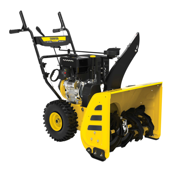
OPERATOR'S MANUAL
MODEL #100680
27 iN. 2-STAgE SNOwbLOwER
REGISTER YOUR PRODUCT ONLINE
at championpowerequipment.com
or visit championpowerequipment.com
READ AND SAVE THiS MANUAL. This manual contains important safety precautions which should be read and understood before operating the product. Failure to
do so could result in serious injury. This manual should remain with the product.
Specifications, descriptions and illustrations in this manual are as accurate as known at the time of publication, but are subject to change without notice.
REV 20200810
Champion Power Equipment, Inc., Santa Fe Springs, CA USA
Advertisement
Table of Contents

Related Manuals for Champion Power Equipment 100680


Summary of Contents for Champion Power Equipment 100680
- Page 1 This manual should remain with the product. Specifications, descriptions and illustrations in this manual are as accurate as known at the time of publication, but are subject to change without notice. REV 20200810 Champion Power Equipment, Inc., Santa Fe Springs, CA USA...
-
Page 2: Table Of Contents
TAbLE Of CONTENTS 100680 - 27 iN. 2-STAgE SNOwbLOwER TAbLE Of CONTENTS Maintenance ..........Engine Maintenance ..........introduction ........... Oil Change ............ -
Page 3: Introduction
100680 - 27 iN. 2-STAgE SNOwbLOwER iNTRODUCTiON SAfETY DEfiNiTiONS Congratulations on your purchase of a Champion Power Equipment The purpose of safety symbols is to attract your attention to (CPE) product. CPE designs, builds, and supports all of our possible dangers. The safety symbols, and their explanations, products to strict specifications and guidelines. -
Page 4: Important Safety Instructions
SAfETY iNSTRUCTiONS 100680 - 27 iN. 2-STAgE SNOwbLOwER iMPORTANT SAfETY iNSTRUCTiONS wARNiNg Sparks can result in fire or electrical shock. wARNiNg When servicing the engine: Cancer and Reproductive Harm – www.P65Warnings.ca.gov Disconnect the spark plug wire and place it where it cannot contact the plug. -
Page 5: Training
SAfETY iNSTRUCTiONS 100680 - 27 iN. 2-STAgE SNOwbLOwER Training – Only fill or drain gasoline outdoors in a well-ventilated area. – DO NOT pump gasoline directly into the snowblower at the gas 1. Read the Operator’s Manual completely before attempting to station. -
Page 6: Operation
SAfETY iNSTRUCTiONS 100680 - 27 iN. 2-STAgE SNOwbLOwER Operation 18. Keep all nuts, bolts and screws tight to be sure the equipment is in safe working condition prior to operation. 1. Do not put hands or feet near or under rotating parts. Keep 19. -
Page 7: Safety Labels
- changed to “87” octane. process magenta This artwork belongs to Champion Power Equipment. The contents are confidential and privileged and shall not be disclosed to or used by or for outside parties without the explicit consent of Champion Power Equipment. -
Page 8: Safety Symbols
SAfETY iNSTRUCTiONS 100680 - 27 iN. 2-STAgE SNOwbLOwER Safety Symbols Some of the following symbols may be used on this product. Please study them and learn their meaning. Proper interpretation of these symbols will allow you to more safely operate the product. - Page 9 SAfETY iNSTRUCTiONS 100680 - 27 iN. 2-STAgE SNOwbLOwER SYmBOL mEaNING hot Surface. To reduce the risk of injury or damage, avoid contact with any hot surface. Open Flame alert. Fuel and its vapors are extremely flammable and explosive. Keep fuel away from smoking, open flames, sparks, pilot lights, heat, and other ignition sources.
-
Page 10: Operation Symbols
SAfETY iNSTRUCTiONS 100680 - 27 iN. 2-STAgE SNOwbLOwER Operation Symbols Some of the following symbols may be used on this product. Please study them and learn their meaning. Proper interpretation of these symbols will allow you to more safely operate the product. -
Page 11: Quickstart Label Symbols
5. Priming the Engine This artwork belongs to Champion Power Equipment. The contents are confidential and privileged and shall not be disclosed to or used by or for 5a. To start the COLD engine: Prime 3-5 times. -
Page 12: Controls And Features
CONTROLS AND fEATURES 100680 - 27 iN. 2-STAgE SNOwbLOwER CONTROLS AND fEATURES Read this operator’s manual before operating your snowblower. Familiarize yourself with the location and function of the controls and features. Save this manual for future reference. Snowblower 10. Impeller 1. - Page 13 CONTROLS AND fEATURES 100680 - 27 iN. 2-STAgE SNOwbLOwER Parts included accessories 6 ft. (1.8 m) Electric Start Power Cord ......
- Page 14 CONTROLS AND fEATURES 100680 - 27 iN. 2-STAgE SNOwbLOwER Part hardware Part hardware Needed hardware Reference Tool Needed Qty. Qty. Speed Control Clip (preassembled) (8-1) Lever M8×40 Hexagon flange bolt (9-1) Snow Discharge 12mm Wrench Chute M8 Hexagon flange lock nut...
-
Page 15: Assembly
ASSEMbLY 100680 - 27 iN. 2-STAgE SNOwbLOwER ASSEMbLY 2–3 Your snowblower requires some assembly. This unit ships from our factory with oil. It must be properly serviced with fuel and oil before operation. If you have any questions regarding the assembly of your snowblower, call our Technical Support Team at 1-877-338-0999. -
Page 16: Cables
ASSEMbLY 100680 - 27 iN. 2-STAgE SNOwbLOwER Cables Upper Handle 1. Cables are disconnected from each other and found on the 1. Fold the upper handle up, making sure the cables pull tight base of the snowblower (near the auger housing) and on the (Fig 5). -
Page 17: Speed Control Connecting Lever
ASSEMbLY 100680 - 27 iN. 2-STAgE SNOwbLOwER 3. Discharge chute bracket should be placed forward as shown (for correct placement). Do not overtighten. Connect discharge chute guide to lower handle with 1 bolt (7-1), and 1 9–2 lock nut (7-2) (Fig. 7). -
Page 18: Add Engine Oil
ASSEMbLY 100680 - 27 iN. 2-STAgE SNOwbLOwER 3. Align the lever and the gear, and then connect the R-clip 1. Place the snowblower on a flat, level surface. (11-1). (Fig. 11B). 2. Remove the oil cap/dipstick and wipe it clean (Fig. 12A). -
Page 19: Add Fuel
ASSEMbLY 100680 - 27 iN. 2-STAgE SNOwbLOwER NOTiCE CAUTiON Synthetic oil may be used after the first oil change. Using Use unleaded gasoline with a minimum octane rating of 87 synthetic oil does not decrease the recommended oil change and an ethanol content of 10% or less by volume. -
Page 20: Operation
OPERATiON 100680 - 27 iN. 2-STAgE SNOwbLOwER OPERATiON Starting the Engine 1. Make sure the engine key (safety lock out) is inserted into the wARNiNg key hole. 2. To start a warm engine: (Fig. 14). Never use the snowblower without first reading and understanding the operating instructions, warnings and 2a. -
Page 21: Stopping The Engine
OPERATiON 100680 - 27 iN. 2-STAgE SNOwbLOwER Operation at High Altitude 4. Stand back and to the right of the unit, pull the starter grip lightly until you feel resistance then pull briskly. Return the The density of air at high altitudes is lower than at sea level. -
Page 22: Control Levers
OPERATiON 100680 - 27 iN. 2-STAgE SNOwbLOwER Control Levers Drive System Your snowblower has 6 forward speeds and 2 reverse to regulate forward and backward motion (Fig. 19). Self-drive control handle. Located on the right side handle (Fig. 18). Forward speeds range from slowest When the snowblower has been put position 1 to fastest position 6. -
Page 23: Adjusting The Snow Discharge Direction And Height
OPERATiON 100680 - 27 iN. 2-STAgE SNOwbLOwER Adjusting the Snow Discharge Direction and Adjusting the Snow Shoes Height Set the height of the auger housing above the ground using the shoes. Change discharge direction: Adjust the shoes to suit the ground conditions: –... -
Page 24: After Use
MAiNTENANCE 100680 - 27 iN. 2-STAgE SNOwbLOwER After Use wARNiNg 1. Check for loose or damaged parts. If required, change Do not cover the machine while the engine and muffler are still damaged parts. hot. 2. Tighten loose screws and nuts. -
Page 25: Cleaning And Adjusting The Spark Plug(S)
MAiNTENANCE 100680 - 27 iN. 2-STAgE SNOwbLOwER 3. Inspect the electrode on the plug. It must be clean and not worn to produce the spark required for ignition. 4. Make certain the spark plug gap is 0.7 - 0.8 mm (0.028 - 0.031 in.). -
Page 26: Adjusting Self-Drive Control Handle Cable
MAiNTENANCE 100680 - 27 iN. 2-STAgE SNOwbLOwER Adjusting Auger Control Cable Check the slack of the tension and adjust accordingly. Make sure that the tension on the auger control cable is adjusted so it has ⁄ ⁄ between in. (6.4-9.5 mm) of movement. This movement can... - Page 27 MAiNTENANCE 100680 - 27 iN. 2-STAgE SNOwbLOwER 5. Remove the base frame cover (1) from the underside of the snowblower by removing the six M6 × 16 screws which secure it (Fig 30). Figure 28A Figure 30 6. Slide the speed adjusting handle to the right (Fig. 31A) and remove the loose belt by cutting it or any remaining belt pieces if the belt has already broken (Fig.
- Page 28 MAiNTENANCE 100680 - 27 iN. 2-STAgE SNOwbLOwER Figure 32A Figure 35 11. Reassemble the support rod by pushing back into place and ensure that it is properly engaged into the friction disc assembly and replace the washer and clip (Fig. 36).
-
Page 29: Replace Auger Drive Belt - Splitting
MAiNTENANCE 100680 - 27 iN. 2-STAgE SNOwbLOwER Replace Auger Drive belt – Splitting The 4. Unscrew the bolt of auger control wire (Fig. 41). Snowblower body (Option 2) Tools required: – Size 10 wrench (included). – Size 12 wrench (included). -
Page 30: Repair Or Replace Friction Disk
MAiNTENANCE 100680 - 27 iN. 2-STAgE SNOwbLOwER 7. Unscrew the bolt on the belt guard (Fig. 44). 10. Install the plastic belt cover (A) using two M6 × 16 bolts (B) set aside from an earlier step. Torque until snug. Do not overtighten or you risk damaging the plastic belt cover (Fig. - Page 31 MAiNTENANCE 100680 - 27 iN. 2-STAgE SNOwbLOwER 2. Remove the base frame cover (1) from the underside of the 5. Carefully position the hex shaft downward and to the left snowblower by removing the six M6 × 16 screws which before carefully sliding the friction disc assembly (5) off the secure it (Fig.
-
Page 32: Lubrication
STORAgE 100680 - 27 iN. 2-STAgE SNOwbLOwER Lubrication Transporting Lubricate the linkage every 10 hours of use and before long-term If the engine has been running, allow it to cool for at least 15 storage. Use 0W-30 oil. minutes before loading the machine on the transport vehicle. -
Page 33: Specifications
SPECifiCATiONS 100680 - 27 iN. 2-STAgE SNOwbLOwER SPECifiCATiONS Oil Specifications DO NOT OVERFILL. Snowblower Specifications Type ............0W-30 Model ............ -
Page 34: Troubleshooting
TROUbLESHOOTiNg 100680 - 27 iN. 2-STAgE SNOwbLOwER TROUbLESHOOTiNg Problem Cause Solution Repeat start attempts with throttle choke Engine flooded. OFF. Engine fails to start. Water in fuel. Drain tank and refill with fresh fuel. Check carefully the start procedure Other. - Page 35 Please register within ten (10) Consequential Damage days from date of purchase. Champion Power Equipment disclaims any obligation to cover any loss of time, use of this product, freight, or any incidental Repair/Replacement Warranty or consequential claim by anyone from using this product.
- Page 36 THE UNITED STATES ENVIRONMENTAL PROTECTION AGENCY (U.S. EPA) AND THE CALIFORNIA AIR RESOURCES BOARD (CARB) EMISSION CONTROL SYSTEM WARRANTY Your Champion Power Equipment (CPE) engine complies with both the U.S. EPA and state of California Air Resources Board (CARB) emissions regulations.
- Page 37 EMISSION CONTROL SYSTEM WARRANTY The following are specific provisions relative to your Emission Control System (ECS) Warranty Coverage. 1. APPLICABILITY: This warranty shall apply to 1995 and later model year California small off-road engines (SORE) (for other states, 1997 and later model year engines). The ECS Warranty Period shall begin on the date the new engine or equipment is delivered to its original, end-use purchaser, and shall continue for 24 consecutive months thereafter.
- Page 38 You must take your CPE engine or the product on which it is installed, along with your warranty registration card or other proof of original purchase date, at your expense, to any Champion Power Equipment dealer who is authorized by Champion Power Equipment, Inc. to sell and service that CPE product during his normal business hours.
Need help?
Do you have a question about the 100680 and is the answer not in the manual?
Questions and answers