Table of Contents
Advertisement
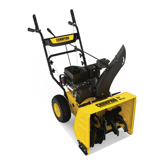
OPERATOR'S MANUAL
MODEL #100434
24 iN. 2-STAgE SNOwbLOwER
REGISTER YOUR PRODUCT ONLINE
at championpowerequipment.com
or visit championpowerequipment.com
READ AND SAVE THiS MANUAL. This manual contains important safety precautions which should be read and understood before operating the product. Failure to
do so could result in serious injury. This manual should remain with the product.
Specifications, descriptions and illustrations in this manual are as accurate as known at the time of publication, but are subject to change without notice.
Made in China - REV 20190529
Champion Power Equipment, Inc., Santa Fe Springs, CA USA
Advertisement
Table of Contents

Related Manuals for Champion Power Equipment 100434


Summary of Contents for Champion Power Equipment 100434
- Page 1 This manual should remain with the product. Specifications, descriptions and illustrations in this manual are as accurate as known at the time of publication, but are subject to change without notice. Made in China - REV 20190529 Champion Power Equipment, Inc., Santa Fe Springs, CA USA...
-
Page 2: Table Of Contents
TAbLE Of CONTENTS 100434 - 24 iN. 2-STAgE SNOwbLOwER TAbLE Of CONTENTS Maintenance ..........Servicing ............introduction ........... Refueling ............Safety Definitions Adding Fuel ............ -
Page 3: Introduction
100434 - 24 iN. 2-STAgE SNOwbLOwER iNTRODUCTiON SAfETY DEfiNiTiONS Congratulations on your purchase of a Champion Power Equipment The purpose of safety symbols is to attract your attention to (CPE) product. CPE designs, builds, and supports all of our possible dangers. The safety symbols, and their explanations, products to strict specifications and guidelines. -
Page 4: Important Safety Instructions
SAfETY iNSTRUCTiONS 100434 - 24 iN. 2-STAgE SNOwbLOwER iMPORTANT SAfETY iNSTRUCTiONS Safe Handling of gasoline To avoid severe injury or property damage use high levels of care wARNiNg while handling gasoline. Gasoline is an extremely flammable substance and the vapors are explosive. Serious personal injury Cancer and Reproductive Harm –... -
Page 5: Clearing A Clogged Discharge Chute
SAfETY iNSTRUCTiONS 100434 - 24 iN. 2-STAgE SNOwbLOwER 4. If the unit should start to vibrate abnormally, stop the engine 22. Be careful while working on the machine or clearing a and check immediately for the cause. Vibration is generally a blockage in the auger or impeller to ensure that fingers and warning of trouble. -
Page 6: Fuel Safety
SAfETY iNSTRUCTiONS 100434 - 24 iN. 2-STAgE SNOwbLOwER fuel Safety When transporting or servicing the snowblower: Make certain that the fuel valve is in the OFF position, the gasoline DANgER tank is empty. Disconnect the spark plug wire. -
Page 7: Safety Labels
50% process magenta This artwork belongs to Champion Power Equipment. The contents are confidential and privileged and shall not be disclosed to or used by or for outside parties without the explicit consent of Champion Power Equipment. -
Page 8: Safety Symbols
SAfETY iNSTRUCTiONS 100434 - 24 iN. 2-STAgE SNOwbLOwER Safety Symbols Some of the following symbols may be used on this product. Please study them and learn their meaning. Proper interpretation of these symbols will allow you to more safely operate the product. - Page 9 SAfETY iNSTRUCTiONS 100434 - 24 iN. 2-STAgE SNOwbLOwER SYmBOL mEaNING hot Surface. To reduce the risk of injury or damage, avoid contact with any hot surface. Open Flame alert. Fuel and its vapors are extremely flammable and explosive. Keep fuel away from smoking, open flames, sparks, pilot lights, heat, and other ignition sources.
-
Page 10: Quickstart Label Symbols
5. Pull the recoil started to start the engine. This artwork belongs to Champion Power Equipment. The contents are confidential and privileged and shall not be disclosed to or used by or for outside parties without the explicit consent of Champion Power Equipment. -
Page 11: Controls And Features
CONTROLS AND fEATURES 100434 - 24 iN. 2-STAgE SNOwbLOwER CONTROLS AND fEATURES Read this operator’s manual before operating your snowblower. Familiarize yourself with the location and function of the controls and features. Save this manual for future reference. Snowblower Engine 1. -
Page 12: Parts Included
CONTROLS AND fEATURES 100434 - 24 iN. 2-STAgE SNOwbLOwER Parts included accessories 6 ft. (1.8 m) Electric Start Power Cord ........1 Chute Clearing Tool ..............1 B Clip and Sheer Pins (spare parts) ........... 4 Tools 10mm × 12mm Double Open End Wrench ........ 2... - Page 13 CONTROLS AND fEATURES 100434 - 24 iN. 2-STAgE SNOwbLOwER Part hardware Part hardware Needed hardware Reference Tool Needed Qty. Qty. M8×45 Hexagon flange bolt 12mm Wrench Discharge chute bracket M8×45 Hexagon flange lock 12mm Wrench Speed Control Clip Lever M6×20 Hexagon flange bolt...
-
Page 14: Assembly
ASSEMbLY 100434 - 24 iN. 2-STAgE SNOwbLOwER ASSEMbLY wheel 1. Slide the left wheel (2-1) onto axle (2-2) as the arrow shows. Your snowblower requires some assembly. This unit ships from our Tread pattern should face forward. Place axle pin (2-3) into factory without oil. -
Page 15: Upper Handle
ASSEMbLY 100434 - 24 iN. 2-STAgE SNOwbLOwER 3. Attach adjustable skid shoes to auger housing. Insert bolts 3. Insert wire clamps (5-3) together and pull to make sure they (3-1) through the auger housing then through the shoe. are connected. (Fig. 5). -
Page 16: Upper Handle
ASSEMbLY 100434 - 24 iN. 2-STAgE SNOwbLOwER Upper Handle 3. Discharge chute bracket should be placed forward as shown (for correct placement). Do not overtighten. Connect 1. Fold the upper handle up, making sure the cables pull tight discharge chute guide to lower handle with 1 bolt (8-1), and 1 (Fig 6). -
Page 17: Snow Discharge Chute
ASSEMbLY 100434 - 24 iN. 2-STAgE SNOwbLOwER 4. Tighten all nuts (10-2). Do not overtighten. 3. Remove the bolts (11-3) and nuts (11-4) on the snow discharge support. Put the snow discharge chute on the base of unit’s body. Attach the snow discharge support using bolts (11-3) and nuts (11-4) (Fig. -
Page 18: Operation
OPERATiON 100434 - 24 iN. 2-STAgE SNOwbLOwER Starting the Engine 4. Check the snow discharge chute by turning it fully in both directions. The discharge chute should rotate freely. Read instructions carefully. wARNiNg 1. Make sure the engine safety key is inserted into the key hole ... -
Page 19: Stopping The Engine
OPERATiON 100434 - 24 iN. 2-STAgE SNOwbLOwER 6. Stand back and to the right of the unit, pull the starter grip wARNiNg lightly until you feel resistance then pull briskly. Return the starter grip gently (Fig. 13C). Never fill fuel tank indoors, with engine running, or until the engine has been allowed to cool for at least 15 minutes after running. -
Page 20: Drive System
OPERATiON 100434 - 24 iN. 2-STAgE SNOwbLOwER Adjusting the Snow Discharge Direction and Self drive control handle Height Change discharge direction: auger control handle Turn the lever counter-clockwise – the snow discharge guide turns to the left. Turn the lever clockwise – the snow discharge guide turns to the right. -
Page 21: Adjusting The Snow Shoes
MAiNTENANCE 100434 - 24 iN. 2-STAgE SNOwbLOwER Adjusting the Snow Shoes CAUTiON Set the height of the auger housing above the ground using the Do not at any time make any adjustment to machine without shoes. first stopping the engine and disconnecting the spark plug Adjust the shoes to suit the ground conditions: wire. -
Page 22: Refueling
MAiNTENANCE 100434 - 24 iN. 2-STAgE SNOwbLOwER EaCh USE wARNiNg — Check oil level Gasoline is highly flammable and explosive, and you can be burned or seriously injured when refueling. EVERY mONTh OR 20 hOURS – Stop engine and keep heat, sparks, and flame away. -
Page 23: Oil Change
MAiNTENANCE 100434 - 24 iN. 2-STAgE SNOwbLOwER Oil Change Drain the engine oil when the engine is warm. Warm oil drains quickly and completely. 1. Turn the fuel valve lever to the OFF position to reduce the possibility of fuel spillage. -
Page 24: Adjusting Auger Control Cable
MAiNTENANCE 100434 - 24 iN. 2-STAgE SNOwbLOwER Adjusting Auger Control Cable Replace Traction Drive belt - Splitting The Snowblower body Check the slack of the tension and adjust accordingly. Make sure that the tension on the auger control cable is adjusted so it has Tools required: ⁄... - Page 25 MAiNTENANCE 100434 - 24 iN. 2-STAgE SNOwbLOwER 3. Remove the 2 bolts (20 mm/30 mm) holding the belt guard (Fig. 24D). Note the spring is loose at this point. Figure 26B 7. Slip the new auger drive belt into the compartment from the...
- Page 26 MAiNTENANCE 100434 - 24 iN. 2-STAgE SNOwbLOwER 8. Ensure belt is seated below the belt guide on the idler pulley 11. Reassemble the support rod by pushing back into place pivot arm (Fig. 28). and ensure that it is properly engaged into the friction disc assembly and replace the washer and clip (Fig.
-
Page 27: Repair Or Replace Friction Disk
MAiNTENANCE 100434 - 24 iN. 2-STAgE SNOwbLOwER Repair or Replace friction Disk 3. Remove the right wheel (2) by removing the axle pin on it (Fig. 33C). NOTiCE If the snowblower fails to drive with the drive control engaged, and performing the drive control cable adjustment fails to correct the problem, the friction disc may need to be replaced. -
Page 28: Lubrication
MAiNTENANCE 100434 - 24 iN. 2-STAgE SNOwbLOwER Storage 6. Unscrew the six M6 × 16 bolts (6) of the friction disc assembly to discard the worn friction wheel rubber ring (7) Never store the machine with gasoline in the fuel tank in a and replace with a new one (Fig. -
Page 29: Specifications
SPECifiCATiONS 100434 - 24 iN. 2-STAgE SNOwbLOwER SPECifiCATiONS Oil Specifications DO NOT OVERFILL. Snowblower Specifications Type ............0W-30 Model ............ -
Page 30: Parts Diagram
SPECifiCATiONS 100434 - 24 iN. 2-STAgE SNOwbLOwER Parts Diagram... -
Page 31: Parts List
SPECifiCATiONS 100434 - 24 iN. 2-STAgE SNOwbLOwER Parts List Part Number Description Qty. Part Number Description Qty. Hexagon Flange Bolt, Hexagon Locking Nut, M8, 30913070165000 25 30313090025000 M8 × 16, Blue Zinc White Zinc Bearing Support, Flange Locking Nut, M6, All... - Page 32 SPECifiCATiONS 100434 - 24 iN. 2-STAgE SNOwbLOwER Part Number Description Qty. Part Number Description Qty. Steering Positioning Plate, Spacer Bushing, Worm 46 23071000210001C 70 23024000195000A Ø158.5 × 4, Black Wheel Plate, Ø29 × Ø25.6 Hexagon Flange Bolt, M6 × Worm Wheel Plate,...
- Page 33 SPECifiCATiONS 100434 - 24 iN. 2-STAgE SNOwbLOwER Part Number Description Qty. Part Number Description Qty. Left Wheel Assembly, 13 Large Synchronous Pulley, 116 23034000185000C 93 23019000100034D × 4.1 inch, Pantone 109C Ø170 Yellow Hexagon Bolt, 117 30913040085000 Hexagon Angle Bushing, M8 ×...
- Page 34 SPECifiCATiONS 100434 - 24 iN. 2-STAgE SNOwbLOwER Part Number Description Qty. Dish Washer, T=2.5, White 142 23032000205000A Zinc 143 23062000270001N Lower Handle, Black Curved Washer, 144 21061000113201A PA6+GF30, Black Flat Head Bolt, 145 23099000035000A M8 × 52, White Zinc Left Upper Handle...
-
Page 35: Engine Parts Diagram
SPECifiCATiONS 100434 - 24 iN. 2-STAgE SNOwbLOwER Engine Parts Diagram... -
Page 36: Engine Parts List
SPECifiCATiONS 100434 - 24 iN. 2-STAgE SNOwbLOwER Engine Parts List Part Number Description Qty. Part Number Description Qty. Flange Bolt M6 × 8 Washer Ø6.4 × Ø13 × 1, 1.5789.0608.1 40 2.03.021.1 Black 26.061100.00.1 Cover, Recoil Starter, Black 21.110001.00 Shaft, Governor Arm 21.061005.00... - Page 37 SPECifiCATiONS 100434 - 24 iN. 2-STAgE SNOwbLOwER Part Number Description Qty. Part Number Description Qty. 80 1.6177.1.06 123 1.5789.0608 Flange Nut M6 Flange Bolt M6 × 8 81 24.040201.00 124 2.06.046 Retainer, Rocker Arm Clamp Ø12 × Ø1 82 23.040010.00 Bolt, Rocker Arm 125 26.061000.00...
-
Page 38: Troubleshooting
TROUbLESHOOTiNg 100434 - 24 iN. 2-STAgE SNOwbLOwER TROUbLESHOOTiNg Problem Cause Solution Repeat start attempts with throttle choke Engine flooded. OFF. Engine fails to start. Water in fuel. Drain tank and refill with fresh fuel. Check carefully the start procedure Other. - Page 39 Consequential Damage electrical components will be free of defects in material and Champion Power Equipment disclaims any obligation to cover workmanship for a period of two years (parts and labor) from any loss of time, use of this product, freight, or any incidental the original date of purchase and 180 days (parts and labor) for or consequential claim by anyone from using this product.
- Page 40 United States Environment Protection Agency (U.S. EPA) Emission Control System Warranty Your Champion Power Equipment (CPE) engine complies with U.S. EPA emission regulations. YOUR WARRANTY RIGHTS AND OBLIGATIONS: The US EPA AND CPE are pleased to explain the Federal Emission Control Systems Warranty on your 2017 small off-road engine and engine powered equipment.
- Page 41 EMISSION CONTROL SYSTEM WARRANTY The following are specific provisions relative to your Emission Control System (ECS) Warranty Coverage. 1. APPLICABILITY: This warranty shall apply to 1997 and later model year small off-road engines. The ECS Warranty Period shall begin on the date the new engine or equipment is delivered to its original, end-use purchaser, and shall continue for 24 consecutive months thereafter.
- Page 42 You must take your CPE engine or the product on which it is installed, along with your warranty registration card or other proof of original purchase date, at your expense, to any Champion Power Equipment dealer who is authorized by Champion Power Equipment, Inc. to sell and service that CPE product during his normal business hours.
Need help?
Do you have a question about the 100434 and is the answer not in the manual?
Questions and answers
I need the augur belt size