
Related Manuals for ASROCK IMB-1312


Summary of Contents for ASROCK IMB-1312
- Page 1 IMB-1312 User Manual Version 1.0 Published January 2019 Copyright©2019 ASRock INC. All rights reserved.
- Page 2 (including damages for loss of profits, loss of business, loss of data, interruption of business and the like), even if ASRock has been advised of the possibility of such damages arising from any defect or error in the documentation or product.
- Page 3 The terms HDMI® and HDMI High-Definition Multimedia Interface, and the HDMI logo are trademarks or registered trademarks of HDMI Licensing LLC in the United States and other countries. CAUTION: RISK OF EXPLOSION IF BATTERY IS REPLACED BY AN INCORRECT TYPE. DISPOSE OF USED BATTERIES ACCORDING TO THE INSTRUCTIONS.
-
Page 4: Table Of Contents
Contents 1 Introduction ............5 1.1 Package Contents ............5 1.2 Specifications ..............6 1.3 Motherboard Layout ............8 1.4 I/O Panel ................ 10 2 Installation ............11 2.1 Screw Holes ..............11 2.2 Pre-installation Precautions ........... 11 2.3 Installation of Memory Modules (DIMM) ......12 2.4 Expansion Slots ............ -
Page 5: Introduction
In case any modifications of this manual occur, the updated version will be available on ASRock website without further notice. You may find the latest VGA cards and CPU support lists on ASRock website as well. ASRock website http://www.asrock.com If you require technical support related to this motherboard, please visit our website for specific information about the model you are using. -
Page 6: Specifications
1.2 Specifications Form Dimensions Micro ATX (9.6-in x 9.6-in) Factor ® Socket LGA 1151 for 8 Intel Core i7/i5/i3/ Processor Celeron (Supports up to 95W) System ® Chipset Intel Q370 1x PCIe x16, 1x PCIe x8, 2x PCIe x4 PCIe * Slot1: Gen3 x16 link, auto switch to x8 link if Slot3 is occupied. - Page 7 6 x USB2.0, 2 x USB3.1 LVDS/ inverter Serial 5 x COM (RS-232) 8 x SATA3 (6.0Gb/s), one is shared with M.2 Internal SATA Key M Connector Parallel 1 (shared with GPIO) GPIO 8 x GPI, 8 x GPO SATA PWR Output Speaker Header...
-
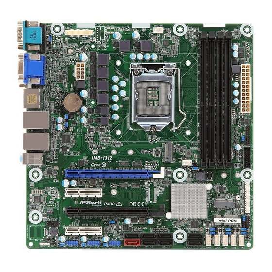
Page 8: Motherboard Layout
LVDS1 BLT_PWM1 PWR_BAT1 CMOS Battery USB 3.1 Top: T: USB1 RJ-45 B: USB2 USB 3.1 Top: T: USB3 LPC1 RJ-45 B: USB4 IMB-1312 CHA_FAN1 PCIE1 BIOS PCIE2 M.2 _2 Industrial PCIE3 mini-PCIe HD_AUDIO1 CLRMOS2 CLRMOS1 PWR_COM4 PWR_COM5 JGPIO_SET1 PCIE4 SPEAKER1... - Page 9 1 : COM Port Pin9 PWR Setting Jumper (PWR_COM1 (For COM Port1)) 2 : Panel Power Select (PNL_PWR1) 3 : BL2 4 : LVDS Panel Connector 5 : Backlight & Amp Volume Control (BLT_VOL1) 6 : Inverter Power Control Wafer (BLT_PWR1) 7 : Backlight Control Level (BLT_PWM1) (CON_LBKLT_CTL) 8 : BL1 9 : Backlight Power Select (LCD_BLT_VCC) (BKT_PWR1)
-
Page 10: I/O Panel
1.4 I/O Panel COM Port (COM1) (RS232/422/485)* USB 3.1 Ports (USB3_3_4) D-Sub Port (VGA1) USB 3.1 Ports (USB3_1_2) LAN RJ-45 Port** DisplayPort (DP1) LAN RJ-45 Port** HDMI Port (HDMI1) Line In (Light Blue) DVI-D Port (DVI1) Line out (Lime) PS/2 Keyboard/Mouse Port Microphone (Pink) * This motherboard supports RS232/422/485 on COM1 port. -
Page 11: Installation
Chapter 2: Installation This is a Micro ATX form factor (9.6” x 9.6”) motherboard. Before you install the motherboard, study the configuration of your chassis to ensure that the motherboard fits into it. Make sure to unplug the power cord before installing or removing the motherboard. -
Page 12: Installation Of Memory Modules (Dimm)
2.3 Installation of Memory Modules (DIMM) This motherboard provides four 288-pin DDR4 (Double Data Rate 4) DIMM slots, and supports Dual Channel Memory Technology. 1. For dual channel configuration, you always need to install identical (the same brand, speed, size and chip-type) DDR4 DIMM pairs. 2. -
Page 14: Expansion Slots
2.4 Expansion Slots There are 4 PCI Express slots, 1 mini-PCIe slots and 2 M.2 sockets on this mother- board. PCIE slots: PCIE1 (PCIE x16 slot) is used for PCI Express x16 lane width cards. PCIE2 (PCIE x4 slot) is used for PCI Express x4 cards. PCIE3 (PCIE x16 slot) is used for PCI Express x8 lane width cards. - Page 15 Installing an expansion card Step 1. Before installing the expansion card, please make sure that the power supply is switched off or the power cord is unplugged. Please read the documentation of the expansion card and make necessary hardware settings for the card before you start the installation. Step 2.
-
Page 16: Jumpers Setup
2.5 Jumpers Setup The illustration shows how jumpers are setup. When the jumper cap is placed on pins, the jumper is “Short”. If no jumper cap is placed on pins, the jumper is “Open”. The illus- tration shows a 3-pin jumper whose pin1 and pin2 are “Short”... - Page 17 COM Port Pin9 PWR Setting Jumpers 1-2 : +5V 2-3 : +12V (3-pin PWR_COM1 (For COM Port1)) (see p.8, No. 1) (3-pin PWR_COM2 (For COM Port2)) (3-pin PWR_COM3 (For COM Port3)) (3-pin PWR_COM4 (For COM Port4)) (3-pin PWR_COM5 (For COM Port5)) (3-pin PWR_COM6 (For COM Port6)) (see p.8, No.
- Page 18 USB Power Setting Jumpers 1-2 : +5V 2-3 : +5VSB (3-pin USB3_PWR3 (For USB3_5_6)) (see p.8, No. 15) (3-pin USB2_PWR1 (For USB2_5_6), USB2_PWR2 (For USB2_7_8)) USB2_PWR3 (For USB2_9_10)) (see p.8, No. 30) (3-pin USB3_PWR1 (For USB3_1_2), USB3_PWR2 (For USB3_3_4)) (see p.8, No. 36) Backlight Power Select (LCD_BLT_VCC) 1-2 : LCD_BLT_VCC : +5V 2-3 : LCD_BLT_VCC : +12V...
-
Page 19: Onboard Headers And Connectors
2.6 Onboard Headers and Connectors Onboard headers and connectors are NOT jumpers. Do NOT place jumper caps over these headers and connectors. Placing jumper caps over the headers and connectors will cause permanent damage of the motherboard! CPU Fan Connector Please connect the CPU fan 4 3 2 1 cable to the connector and... - Page 20 RESET (Reset Switch): Connect to the reset switch on the chassis front panel. Press the reset switch to restart the computer if the computer freezes and fails to perform a normal restart. PLED (System Power LED): Connect to the power status indicator on the chassis front panel. The LED is on when the system is operating.
- Page 21 Front Panel Audio Header This is an interface for front panel audio cable that allows (9-pin HD_AUDIO1) convenient connection and (see p.8 No. 34) control of audio devices. 1. High Definition Audio supports Jack Sensing, but the panel wire on the chassis must support HDA to function correctly.
- Page 22 Printer Port / GPIO Header (25-pin LPT_GPIO1) (see p.8 No. 20) Printer Port: GPIO: PIN Signal Name PIN Signal Name SLCT GPIO70 BUSY GPIO71 ACK# GPIO72 SPD7 SPD6 GPIO87 SPD5 GPIO86 SPD4 GPIO85 SPD3 JGPIOPWR GPIO84 SLIN# SPD2 JGPIOPWR GPIO83 PINIT# SPD1 GPIO73...
- Page 23 3W Audio Output Wafer (4-pin SPEAKER1) (see p.8 No. 33) Signal Signal Signal Signal Name Name Name Name OUTRP OUTLP OUTLN OUTRN LVDS Connector (40-pin LVDS1) (see p.8 No. 4) * PD (Panel Detection): Connect this pin to LVDS Panel’s Ground pin to detect Panel detection.
-
Page 24: Uefi Setup Utility
Chapter 3: UEFI SETUP UTILITY 3.1 Introduction This section explains how to use the UEFI SETUP UTILITY to configure your system. The UEFI chip on the motherboard stores the UEFI SETUP UTILITY. You may run the UEFI SETUP UTILITY when you start up the computer. Please press <F2>... -
Page 25: Navigation Keys
3.1.2 Navigation Keys Please check the following table for the function description of each navigation key. Navigation Key(s) Function Description Moves cursor left or right to select Screens Moves cursor up or down to select items + / - To change option for the selected items <Enter>... -
Page 26: Advanced Screen
3.3 Advanced Screen In this section, you may set the configurations for the following items: CPU Configu- ration, Chipset Configuration, Storage Configuration, Super IO Configuration, AMT Configuration, ACPI Configuration, USB Configuration and Trusted Computing. Setting wrong values in this section may cause the system to malfunction. -
Page 27: Cpu Configuration
3.3.1 CPU Configuration Intel Hyper Threading Technology Intel Hyper Threading Technology allows multiple threads to run on each core, so that the overall performance on threaded software is improved. Active Processor Cores Select the number of cores to enable in each processor package. CPU C States Support Enable CPU C States Support for power saving. - Page 28 Intel Turbo Boost Technology Use this item to enable or disable Intel Turbo Boost Mode Technology. Turbo Boost Mode allows processor cores to run faster than marked fre- quency in specific conditions. The default value is [Enabled]. CPU Thermal Throttling You may select [Enabled] to enable CPU internal thermal control mechanism to keep the CPU from overheating.
-
Page 29: Chipset Configuration
3.3.2 Chipset Configuration Primary Graphics Adapter This allows you to select [Onboard] or [PCI Express] as the boot graphic adapter priority. The default value is [PCI Express]. Above 4G Decoding Enable or disable 64bit capable Devices to be decoded in Above 4G Ad- dress Space (only if the system supports 64 bit PCI decoding). - Page 30 Active LVDS Use this to enable or disable the LVDS. The default value is [Disabled]. Set the item to [enable]. Then press <F10> to save the setting and restart the system. Now the default value of Active LVDS is changed to ENABLE (F9 load default is also set to ENABLE) Change the setting from [Enable] to [Disable], and then press <F10>...
-
Page 31: Storage Configuration
3.3.3 Storage Configuration SATA Controller(s) Use this item to enable or disable the SATA Controller feature. SATA Mode Selection Use this to select SATA mode. The default value is [AHCI Mode]. AHCI (Advanced Host Controller Interface) supports NCQ and other new features that will improve SATA disk perfor- mance. -
Page 32: Super Io Configuration
3.3.4 Super IO Configuration COM1 Configuration Use this to set parameters of COM1. Type Select Use this to select COM3 port type: [RS232], [RS422] or [RS485]. COM2 Configuration Use this to set parameters of COM2. COM3 Configuration Use this to set parameters of COM3. COM4 Configuration Use this to set parameters of COM4. -
Page 33: Amt Configuration
3.3.5 AMT Technology AMT BIOS Features Use this to enable or disable Intel(R) Active Management Technology BIOS Extension. The default is [Enabled]. ASF support Use this to enable or disable Alert Specification Format. The default is [En- abled]. USB Provisioning of AMT Use this to enable or disable AMT USB Provisioning. - Page 34 Force Secure Erase Use this to enable or disable Force Secure Erase on next boot. The de- fault is [Disabled]. OEM Flags Settings MEBx hotkey Pressed Use this to enable or disable MEBx hotkey press. The default is [Disabled]. MEBx Selection Screen Use this to enable or disable MEBx Selection Screen.
-
Page 35: Acpi Configuration
3.3.6 ACPI Configuration Suspend to RAM Use this item to select whether to auto-detect or disable the Suspend-to- RAM feature. Select [Auto] will enable this feature if the OS supports it. PCIE Devices Power On Use this item to enable or disable PCIE devices to turn on the system from the power-soft-off mode. -
Page 36: Usb Configuration
3.3.7 USB Configuration Legacy USB Support Use this option to select legacy support for USB devices. There are two configuration options: [Enabled] and [UEFI Setup Only]. The default value is [Enabled]. Please refer to below descriptions for the details of these two options: [Enabled] - Enables support for legacy USB. -
Page 37: Trusted Computing
3.3.8 Trusted Computing Security Device Support Enable or disable BIOS support for security device. -
Page 38: Hardware Health Event Monitoring Screen
3.4 Hardware Health Event Monitoring Screen In this section, it allows you to monitor the status of the hardware on your system, including the parameters of the CPU temperature, motherboard temperature, CPU fan speed, chassis fan speed, and the critical voltage. CPU_FAN1 Setting This allows you to set CPU fan 1’s speed. -
Page 39: Security Screen
3.5 Security Screen In this section, you may set, change or clear the supervisor/user password for the system. Supervisor Password Set or change the password for the administrator account. Only the ad- ministrator has authority to change the settings in the UEFI Setup Utility. Leave it blank and press enter to remove the password. -
Page 40: Boot Screen
3.6 Boot Screen In this section, it will display the available devices on your system for you to config- ure the boot settings and the boot priority. Boot From Onboard LAN Use this item to enable or disable the Boot From Onboard LAN feature. Setup Prompt Timeout This shows the number of seconds to wait for setup activation key. - Page 41 CSM (Compatibility Support Module) Enable to launch the Compatibility Support Module. Please do not disable unless you’re running a WHCK test. Launch PXE OpROM Policy Select UEFI only to run those that support UEFI option ROM only. Select Legacy only to run those that support legacy option ROM only. Select Do not launch to not execute both legacy and UEFI option ROM.
-
Page 42: Exit Screen
3.7 Exit Screen Save Changes and Exit When you select this option, it will pop-out the following message, “Save configuration changes and exit setup?” Select [OK] to save the changes and exit the UEFI SETUP UTILITY. Discard Changes and Exit When you select this option, it will pop-out the following message, “Discard changes and exit setup?”... -
Page 43: Software Support
Click on a specific item then follow the installation wizard to install it. 4.2.4 Contact Information If you need to contact ASRock or want to know more about ASRock, you’re welcome to visit ASRock’s website at http://www.asrock.com; or you may con-...
Need help?
Do you have a question about the IMB-1312 and is the answer not in the manual?
Questions and answers