Advertisement
Available languages
Available languages
Quick Links
(ITA) Manuale d' Installazione, Uso e Manutenzione per
"UTILIZZATORE" e "TECNICO INSTALLATORE SPECIALIZZATO"
SIGILLO DI RESPONSABILITA' e RIMOZIONE DELLO STESSO
Un "Sigillo di Responsabilità" viene saldamente ed accuratamente applicato ad ogni attacco prodotto da
esclusivamente dall' utilizzatore originario in persona. La rimozione del "SIGILLO DI RESPONSABILITA'"
rappresenta infatti la prova della piena, diretta, attenta e consapevole presa visione della totalità delle
parti costituenti il "MANUALE DI INSTALLAZIONE, USO E MANUTENZIONE" inserito nella confezione del
prodotto stesso, in particolare l'avvenuta presa visione delle informative di avvertenza contenute nei
paragrafi e riquadri evidenziati con la dicitura "
riguardanti i rischi di utilizzo per l'utilizzatore e/o terze parti e delle clausole di "LIMITAZIONE DELLE
Nel caso in cui il "Sigillo di Responsabilità" non fosse presente sull' attacco acquistato, si prega di non
utilizzare il prodotto, contattare immediatamente l'azienda ATK RACE S.R.L. all' indirizzo e-mail
"customercare@atkbindings.com" e attendere istruzioni su come procedere all' utilizzo del prodotto.
L' "utilizzatore originario" si assume inoltre la assoluta responsabilità di consegnare questo "MANUALE
DI INSTALLAZIONE, USO E MANUTENZIONE" ad eventuali utilizzatori secondari di questo prodotto
(anche se temporanei) e di verificare che abbiano ricevuto la corretta formazione sulle modalità di
utilizzo del prodotto oltre ad aver compreso in maniera completa ed inequivocabile tutte le parti
ATK RACE S.R.L. Via della Fisica 36, 41042, Spezzano di Fiorano (MO), ITALY. Riproduzione vietata. REV02 del 05-12-2019
MODELLO ATTACCO:
ATTENZIONE!
ATK RACE S.R.L. in fase di confezionamento.
La rimozione di questo sigillo DEVE ESSERE EFFETTUATA
RESPONSABILITA' SUL PRODOTTO" del produttore.
costituenti questo manuale.
CATEGORIA PRODOTTO:
CODICE PRODOTTO:
FORATURA PUNTALE:
FORATURA TALLONIERA:
LARGHEZZA MAX CONSIGLIATA
ATTENZIONE!" o "
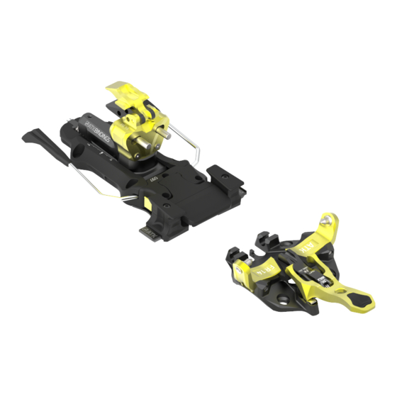
FR14 – 365 GR
FREETOURING
FR14Y.XXX
(xxx=097,102,108,120)
P3-P3- H1-H1
SCI SOTTO PIEDE:
ATTENZIONE! PERICOLO!"
H-H-H-H
120 MM
Advertisement

Related Manuals for ATK BINDINGS FR14


Summary of Contents for ATK BINDINGS FR14
- Page 1 (ITA) Manuale d’ Installazione, Uso e Manutenzione per “UTILIZZATORE” e “TECNICO INSTALLATORE SPECIALIZZATO” MODELLO ATTACCO: FR14 – 365 GR CATEGORIA PRODOTTO: FREETOURING CODICE PRODOTTO: FR14Y.XXX (xxx=097,102,108,120) FORATURA PUNTALE: P3-P3- H1-H1 FORATURA TALLONIERA: H-H-H-H LARGHEZZA MAX CONSIGLIATA SCI SOTTO PIEDE: 120 MM ATTENZIONE! SIGILLO DI RESPONSABILITA’...
- Page 2 Italy). Essi rispondono inoltre alle esigenze di tutti coloro i quali ritengono fondamentali i requisiti che contraddistinguono l’intera gamma dei prodotti ATK BINDINGS®: leggerezza, prestazioni e affidabilità. Tuttavia, per vostro interesse e sicurezza personale, vi invitiamo a leggere attentamente le avvertenze e seguire le istruzioni di seguito riportate.
- Page 3 2| AVVERTENZE E RACCOMANDAZIONI GENERALI ATTENZIONE! PERICOLO! Prima di procedere con qualsiasi operazione relativa ad installazione o utilizzo, assicurarsi di aver compreso integralmente quanto scritto in questo manuale. In caso di dubbi, incertezze o necessità di comunicazioni generiche, si prega di contattare i nostri uffici all’indirizzo e-mail “customercare@atkbindings.com”...
- Page 4 Gli attacchi ATK® sono realizzati e testati in base a scarponi con inserti di aggancio standard in ottimo stato e di dimensioni originali; l’utilizzo di scarponi con inserti non standard o particolarmente usurati modifica il funzionamento degli attacchi e può creare un rischio per l’utilizzatore: prima di ogni utilizzo verificare lo stato d’...
- Page 5 3| INSTALLAZIONE, SETTAGGIO E TARATURA 3.1| INSTALLAZIONE ATTENZIONE! Questo attacco e gli accessori ad esso abbinati possono essere installati, settati e/o tarati esclusivamente da un “TECNICO INSTALLATORE SPECIALIZZATO”. Il “Tecnico Installatore Specializzato” è un qualsiasi tecnico operante nel mondo dello sci/scialpinismo che sia dotato dei seguenti requisiti minimi: 1.
- Page 6 3.2| SETTAGGIO 3.2.1 | SETTAGGIO: COME REGOLARE LA POSIZIONE DELLA TALLONIERA ATTENZIONE! PERICOLO Il modello di attacco “FR14” è dotato del sistema “E.R.S.” (ELASTIC RESPONSE SYSTEM), sviluppato per ottenere una ammortizzazione elastica dell’insieme sci- scarpone-attacco in caso di compressioni e/o flessioni dello sci (CIRCA 8 mm!).
- Page 7 5) Sganciare completamente lo scarpone dall’ attacco e poi riagganciarlo nuovamente per verificare la corretta distanza tra scarpone e talloniera: lo spessimetro da 4 mm deve entrare senza forzature e allo stesso tempo annullare qualsiasi luce tra scarpone e talloniera. (FIG. 1,2,3) FIGURA 3 FIGURA 1 FIGURA 2...
- Page 8 ATTENZIONE! PERICOLO! Con lo scarpone agganciato al puntale in modalità di salita, verificare che RANGE DI ruotando lo scarpone verso la punta dello sci, esso risulti libero di compiere ROTAZIONE almeno 90° di rotazione prima che la LIBERA punta dello scarpone entri in contatto con il leveraggio frontale stesso.
- Page 9 L’ attacco “FR14” è dotato di un sistema di sgancio VERTICALE (My) e di un sistema di sgancio LATERALE (Mz), indipendenti ed entrambi alloggiati nella talloniera.
- Page 10 3.3.1 | TARATURA DEI SISTEMI DI SGANCIO ATTENZIONE! PERICOLO! La taratura dei sistemi di sgancio può essere effettuata esclusivamente da un “TECNICO INSTALLATORE SPECIALIZZATO”. La taratura dei sistemi di sgancio deve essere effettuata tenendo conto delle caratteristiche fisiche e prestazionali dell’utilizzatore.
- Page 11 3.3.1.2 | TARATURA DEL SISTEMA DI SGANCIO LATERALE (Mz) La taratura del valore di sgancio Laterale (Mz) deve essere effettuata tramite la registrazione della vite posizionata alla estremità posteriore della talloniera (impronta PH2 o PZ3, utilizzare inserto di buona qualità) (FIGURA A LATO).
- Page 12 4.1 | MODALITA’ DI UTILIZZO DELLO SKI BRAKE POSTERIORE ATTENZIONE! PERICOLO! Prima di ogni utilizzo verificare la corretta lubrificazione dei piani di scorrimento e richiamo dello ski- brake per evitare malfunzionamenti durante l’uso (vedi paragrafo manutenzione ordinaria). Tutte le operazioni di gestione dello ski-brake devono essere effettuate manualmente! 4.1.1 | ASSETTO DI CAMMINATA/SALITA 1) Dall’assetto di sciata/discesa (FIGURA 6), premere manualmente sul selettore laterale portandolo alla fine della sua corsa elastica (FIGURA 7).
- Page 13 4.1.2 | ASSETTO DI SCIATA/DISCESA Dall’ assetto di salita, operare con questa sequenza (Figura 10): 1) Premere il pedale dello ski brake a fine corsa verso lo sci 2) Premere il selettore laterale fino a fine corsa. 3) Rilasciare delicatamente il pedale dello ski brake. 4) Rilasciare il selettore laterale.
- Page 14 Posizionare lo ski brake posteriore in modalità di salita/camminata come indicato al paragrafo 4.1.1. Posizionare la talloniera in una delle configurazioni illustrate in FIGURA 11 ruotandone manualmente il corpo superiore o lo sportellino alzatacco. FIGURA 11 WWW.ATKBINDINGS.COM | PROUDLY MADE IN ITALY SINCE 2007...
- Page 15 Verificare che il puntale si trovi nella configurazione illustrata in FIGURA 12, pronto ad accogliere lo scarpone e libero da ghiaccio, neve o detriti; se così non fosse, premere manualmente con energia sulla leva frontale fino al raggiungimento della posizione stabilizzata illustrata in FIGURA 12.
- Page 16 Tirare DELICATAMENTE la leva frontale verso di sé fino alla stabilizzazione in posizione di salita/camminata per bloccare il puntale sullo scarpone e permettere la camminata, come mostrato in FIGURA 16. FIGURA 16 ATTENZIONE! Prima di procedere con la salita è necessario accertarsi che la leva si trovi nella posizione stabilizzata illustrata in FIGURA 17 con l’indicatore posizionato sulla scritta “WALK”.
- Page 17 4.3| ATTACCO IN ASSETTO DI DISCESA/SCIATA ATTENZIONE! PERICOLO! La corretta modalità di utilizzo dell’attacco in “ASSETTO DI DISCESA” è quella riportata al paragrafo 4.3 di questo manuale. Questa modalità di utilizzo può permettere lo sgancio dell’attacco in caso di cadute rovinose: è...
- Page 18 Avvicinare la punta della scarpone al puntale, portando le due sedi dell’inserto metallico anteriore dello scarpone in corrispondenza dei puntalini di aggancio dell’attacco (FIGURA 20). Da questa posizione, premere la punta scarpa verso il basso (verticalmente) generando lo scatto del sistema elastico che andrà...
- Page 19 Premere poi con il tacco dello scarpone sulle spine di aggancio della talloniera fino ad ottenere l’aggancio completo rappresentato in FIG.24. FIGURA 24 4.4| COME USCIRE DALL’ ATTACCO DA SCI ATTENZIONE! PERICOLO! Durante le operazioni di apertura dell’attacco, trattenere saldamente con una mano lo sci che si ci appresta a separare dallo scarpone onde evitare che una volta aperto l’attacco lo sci si diriga a valle fuori controllo, rappresentando un grave pericolo per l’utilizzatore e/o terze parti che potrebbero essere colpite dallo sci.
- Page 20 FIGURA 27 4.5| COME UTILIZZARE IL RAMPANT ATK® ATTENZIONE! PERICOLO! I rampant sono da utilizzarsi solo in determinate condizioni di terreno; condizioni di neve non adatte all’ utilizzo di questo accessorio potrebbero causare gravi danni al materiale, e comportare un pericolo per l’utilizzatore e/o terze parti.
- Page 21 5| ACCESSORI PER L’ ATTACCO “FR14” La gamma ATK® è completata da una serie di accessori che incrementano il comfort e le prestazioni dei nostri attacchi; è possibile trovare tutte le informazioni, istruzioni e video alla pagina www.atkbindings.com 6| CURA, CONSERVAZIONE E MANUTENZIONE ATTENZIONE! Lubrificare periodicamente i piani di richiamo dello ski stopper posteriore con grasso originale ATK®...
- Page 22 Premesso che gli attacchi ATK® non sono certificati da alcun ente certificatore in quanto non rispondenti a standard previsti da alcuna normativa DIN /ISO relativa alla sicurezza, la garanzia non opera in ipotesi di: - errato montaggio o montaggio effettuato da parte di un soggetto che non sia un “TECNICO INSTALLATORE SPECIALIZZATO”...
- Page 23 8| LIMITAZIONE DELLE RESPONSABILITA’ SUL PRODOTTO ATTENZIONE! PERICOLO! L’ UTILIZZATORE è pienamente consapevole che gli attacchi ATK® NON RISPONDONO AD ALCUNA NORMATIVA DIN/ISO RELATIVA ALLA SICUREZZA ed in particolar modo NON SODDISFANO né le specifiche di sicurezza richieste dalla normativa DIN/ISO 11088, né...
- Page 24 (ENG) INSTALLATION, USE and MAINTENANCE GUIDEBOOK for the “USER” and the “SPECIALIZED TECHNICIAN” BINDING MODEL: FR14 – 365 GR PRODUCT SEGMENT: FREETOURING PRODUCT CODE: FR14Y.XXX (xxx=097,102,108,120) TOE PATTERN: P3-P3- H1-H1 HEEL PATTERN: H-H-H-H MAX SUGGESTED SKI WIDTH UNDERFOOT: 120 MM...
- Page 25 Fiorano Modenese (Modena, Italy). They meet the needs of all those who consider fundamental the requirements that distinguish the entire range of ATK BINDINGS® products: lightness, performance and reliability.
- Page 26 2| GENERAL WARNINGS AND RECOMMENDATIONS WARNING! DANGER! Before proceeding with any operation regarding the installation or use of the product, please make sure that you have fully understood what is written and explained in this guidebook. In case of any doubts and/or uncertainties, please contact ATK® at the e-mail address "customercare@atkbindings.com"...
- Page 27 In the practice of ski mountaineering, dangerous and/or unpredictable situations may occur; never overestimate your capabilities, never ski if sick of wounded or under the effect of alcohol, medicines or drugs. The ATK® bindings are realized for, and tested in combination with, boots provided with standard “TECH INSERTS”...
- Page 28 3| INSTALLATION, ADJUSMENT AND CALIBRATION 3.1| INSTALLATION WARNING! DANGER! These bindings and the connected accessories can be exclusively installed, adjusted or calibrated by a “SPECIALIZED TECHNICIAN” A “SPECIALIZED TECHNICIAN” is any technician operating in the ski/ski touring business field provided with the following minimum requirements: 1) Is in possession of the original ATK®...
- Page 29 3.2| ADJUSTMENT 3.2.1| ADJUSTMENT: HOW TO ADJUST THE HEEL PART POSITION WARNING! DANGER! The binding model “FR14” is provided with the “E.R.S.” system (ELASTIC RESPONSE SYSTEM), developed to support an aggressive and heavy charge skiing style with an elastic response to compressions and jumps, improving the ski control, precision and flex performance.
- Page 30 5. Completely release the boot and step in again to doublecheck with the 4mm gauge that the boot-heel distance is correct: the gauge must enter the space without forcing and there must not be any left room in between boot, gauge and heel. (Pictures 1, 2, 3) PICTURE 1 PICTURE 3 PICTURE 2...
- Page 31 WARNING! DANGER! Hook the boot at the binding and set it for the uphill walking mode. Rotate the boot on the toe up to BOOT FREE the front end of the rotation- range and verify that the boot is ROTATION performing at least a 90°...
- Page 32 3.3| RELEASE SYSTEMS WARNING! DANGER! This binding model DOES NOT COMPLY WITH ANY DIN/ISO SAFETY STANDARD NOR ANY SAFETY CERTIFICATION. In particular, this binding does comply with DIN/ISO 11088 and/or DIN/ISO 13992 safety standards. The release values set on the binding must be considered as INDICATIVE: the real release value may sensibly differ from the shown one, variate during the entire life of the product and/or variate according to the use and/or wear and tear conditions.
- Page 33 3.3.1| RELEASE SYSTEMS SETTING WARNING! DANGER! The adjustment of the release systems can be performed exclusively by a “SPECIALIZED TECHNICIAN” The adjustment of the release systems must be performed accordingly with the physical and performance characteristics of the User. ...
- Page 34 3.3.1.2| LATERAL RELEASE SYSTEM CALIBRATION (Mz) The lateral release system adjustment can be performed through the back screw shown by the PICTURE ON THE SIDE (use a good quality PH2 or PZ3 insert). The set release value is shown through the upper window (PICTURE ON THE SIDE, e.g.
- Page 35 4.1| HOW TO USE THE REAR SKI BRAKES WARNING! DANGER! Before proceeding with your activities, always check the proper lubrication of the brake’s arms recall walls in order to avoid malfunctions (see at chapter 6). Any operation on the brakes must be performed MANUALLY! 4.1.1 WALK/UP-HILL MODE 1) From ski mode (PICT.6), manually press on the side button, moving it to the end of its sliding range (PICT.7).
- Page 36 4.1.2 SKI MODE In order to set the brake in ski mode starting from the walk mode, operate as follows (PICT.10): 1) Push the brake pedal all the way down to the ski. 2) Push the side button up to the end of its sliding range.
- Page 37 Set the ski brake in walk mode as shown at paragraph 4.1.1 Position the heel part in one of the configurations shown at “PICTURE 11”, rotating manually the heel head and stabilizing the heel flaps into its seats. PICTURE 11 WWW.ATKBINDINGS.COM | PROUDLY MADE IN ITALY SINCE 2007...
- Page 38 Check that the toe part is in the position shown at PICTURE 12, ready to receive the boot, free from ice, snow or other debris. If toe is not in the proper position, manually press on the front locking lever in order to reach the stabilized position shown at PICTURE 12.
- Page 39 Slightly pull the front locking lever towards the boot tip up to the uphill stabilized position in order to lock the binding on the boot and allow the ascent, as shown at PICTURE 16. PICTURE 16 WARNING! Before approaching any up-hill, always check that the front locking lever is stabilized in the locked position (WALK), as shown at PICTURE 17.
- Page 40 4.3| DOWN-HILL MODE WARNING! DANGER! The correct setting of the binding for the DOWNHILL MODE is explained at paragraph 5.2 of this manual. This use modality may allow the release of the binding in case of ruinous falls: NEVER SKI with the binding set for the UP-HILL WALKING MODE in order to avoid the deactivation or exclusion of the release systems of the binding! ...
- Page 41 Move the boot tip towards the toe part, matching the front TECH insert seats with the toe hooking pins (PICTURE 20). From this position, vertically push on the toe part to step in. (PICTURE 21/22). Rotate a few times the boot in order to check the proper boot-binding coupling, as shown at PICTURE 22. PICTURE 20 PICTURE 21 PICTURE 22...
- Page 42 Press on the heel part of the binding in order to step in and to obtain the complete hooking of the boot, as shown at PICTURE 24. PICTURE 24 4.4| HOW TO GET OUT FROM THE BINDING WARNING! DANGER! ...
- Page 43 PICTURE 26 PICTURE 27 4.5| HOW TO USE THE ATK® CRAMPONS WARNING! DANGER! Crampons must be used only with proper snow conditions; improper snow conditions could lead to heavy damages to the material and create a greater danger for the user or third parties. ...
- Page 44 5| “FR14” BINDING ACCESSORIES The ATK® collection is completed by a series of accessories that increase the comfort and performance of the bindings; these accessories and the information about the same can be found at the corporate webpage www.atkbindings.com 6| CARE, MAINTENANCE AND STORAGE WARNING! Remember to periodically lubricate the rear brake recall sledges with the original ATK®...
- Page 45 7| ATK WARRANTY TERMS ATK® guarantees that the product is free from any manufacturing or material defects for a period of two years (2) (pursuant to Italian Legislative Decree n. 24/02) starting from the date of purchase throughout an authorized dealer of ATK® products. The effective date of the warranty must be supported by the proof of purchase: without the original proof of purchase, the temporal effect will start from the date in which the product left the ATK®...
- Page 46 Based on the product state, ATK® will be free to choose the best solution in between replacing the full product, a part of the same or just repair it. An additional warranty period of 6 months is granted on the parts replaced by ATK® during an official service operation, does not matter if under warranty, partial warranty or the customer charge.
- Page 47 8| LIMITATION OF LIABILITY ON THE PRODUCT WARNING! DANGER! The USER is fully aware that the ATK® bindings DO NOT COMPLY WITH ANY DIN/ISO SAFETY STANDARD. In particular, these do not comply with DIN/ISO 11088 and DIN/ISO 13992 safety standards. By purchasing such products in a conscious and informed way as provided by this “INSTALLATION, USE and MAINTENANCE GUIDEBOOK”, the USER expressively accepts without any reserve all the risks arising from the characteristics of the products, relieving...
- Page 48 FR14 2020 “AL09” FREERIDE SPACER IN ACTION WWW.ATKBINDINGS.COM | PROUDLY MADE IN ITALY SINCE 2007...
Need help?
Do you have a question about the FR14 and is the answer not in the manual?
Questions and answers