Advertisement
Quick Links
S
DATE INSTALLED: ____________________________________________________________________
TANK NUMBER: _____________________________________________________________________
MINIMUM TANK READOUT: ________________________________________________________
MAXIMUM TANK READOUT: ________________________________________________________
ALARM 1
ALARM 2
ALARM 3
ALARM 4
CANADA
Garnet Instruments
286 Kaska Road
Sherwood Park, AB T8A 4G7
L
EE
EVE
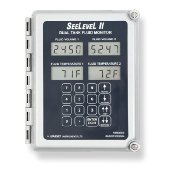
Tank Fluid Monitor
MODEL 900-D4D DUAL
MANUAL
IMPORTANT OPERATOR INFORMATION
ALARM
HIGH VOLUME
USA
Garnet US Inc.
5360 Old Granbury Road
Granbury, TX 76049
L II
ALARM
LOW VOLUME
garnetinstruments.com
1-800-617-7384
TM
Normally Open or
Normally Closed
□
□
NO
NC
□
□
NO
NC
□
□
NO
NC
□
□
NO
NC
Advertisement

Related Manuals for Garnet SeeLevel II 900-D4D DUAL


Summary of Contents for Garnet SeeLevel II 900-D4D DUAL
- Page 1 Normally Closed □ □ ALARM 1 □ □ ALARM 2 □ □ ALARM 3 □ □ ALARM 4 CANADA garnetinstruments.com Garnet US Inc. Garnet Instruments 5360 Old Granbury Road 1-800-617-7384 286 Kaska Road Granbury, TX 76049 Sherwood Park, AB T8A 4G7...
-
Page 2: Table Of Contents
GARNET L II Tank Fluid Monitor MODEL 900-D4 SINGLE Table of Contents CHAPTER 1 - OVERVIEW .....................3 CHAPTER 2 - SYSTEM DESCRIPTION ..............4 CHAPTER 3 - KEYPAD OPERATING INSTRUCTIONS ........10 CHAPTER 4 - INSTALLATION GUIDE ..............19 CHAPTER 5 - TROUBLESHOOTING GUIDE ............20 CHAPTER 6 - MASTER CODE ................... -
Page 3: Chapter 1 - Overview
CHAPTER 1 - OVERVIEW ongratulations on purchasing the Garnet Instruments Model 900 S L II ™ Fluid Monitor for Tanks. The S L II ™ represents the latest in state of the art liquid monitoring equipment for stationary tank applications. The S L II ™... -
Page 4: Chapter 2 - System Description
CHAPTER 2 - SYSTEM DESCRIPTION he SeeLeveL II consists of a sender bar, a donut shaped float, a fiber optic interconnect cable, and a display. The sender bar is mounted vertically in the tank with the float sliding up and down around it in accordance with the fluid level. - Page 5 IMPORTANT NOTICE: SENDER BAR LIMITS OF RESISTIVITY The temperature of the product in the tank should be limited to approximately +90°C (+194°F). Damage to the float and sender bar can occur if this value is exceeded. The float and tube used in the manufacturing of the sender bar is polyethylene.
- Page 6 to show any volume units (for example, barrels), so up to 9,999 can be shown, with the decimal able to be as 9.999, 99.99, 999.9, or 9999 with no decimal. The volume is programmed using the keypad, and a chart showing inches of level versus barrels of volume for the tank is required.
- Page 7 • To select °F or °C for the temperature display. • To program the 4-20 mA outputs. • To set the alarm points. • To program the gauge calibration. • To enter the security codes which control access to the various gauge functions.
- Page 8 The other two 4-20 mA outputs always indicate the temperature as shown on the temperature displays. An output of 4.00 mA corresponds to -54.4°F (-48°C) and an output of 20.00 mA corresponds to +233.6°F (+112°C), for a scale of 18.0 °F/mA or 10.0°C/mA.
- Page 9 Unlike the digital display, the 1-5V signal is analog, so there may be some degradation in accuracy with it. Consequently, the remote equipment may read slightly different than the gauge display. Unlike the digital display, the 1-5V signal is analog, so there may be some degradation in accuracy with it.
-
Page 10: Chapter 3 - Keypad Operating Instructions
CHAPTER 3 - KEYPAD OPERATING INSTRUCTIONS he keypad consists of the 16 buttons on the front of the display, and is used for the following functions: 1. To show inches, alarm status, and battery condition as described in the previous chapter. 2. - Page 11 so he can turn the gauge on, which saves the tank owner the trouble of having to travel out to the tank to turn on the gauge. The initial code out the door is 1234; this can be changed with the master code. 2.
- Page 12 To access the Short User Code (SUC) menu (display on/off & °F/°C selection): 1. Press and hold ENTER until “SECU COdE” appears (this will take approximately 5 seconds). 2. Enter the 4 digit short user security code (it will be shown as you enter it) and press ENTER.
- Page 13 displays, A1 and A2 are driven by the total volume, and A3 and A4 are driven by the interface volume. For dual displays, A1 and A2 are driven by the left volume, and A3 and A4 are driven by the right volume. The display shows the alarm number, the polarity, high or low set point, and the alarm set point.
- Page 14 if the calibration is entered with 2 numbers after the decimal point, then the 4-20 full scale value must also have 2 numbers after the decimal point as well. The display will show “dECI” after ENTER is pressed if the decimals do not match, if this occurs simply re-enter the correct value.
- Page 15 previous code reappears. If the number of digits is correct, then “Stor” will be shown momentarily and the new code will be stored. 5. COPY MENU: To access the copy menu, press ↓↓ FAST DOWN until the display shows “COPY“. This allows remote copying or programming by releasing control of the memory so that the 900M remote programmer can access it.
- Page 16 from a single value. 12. Determine the volume corresponding to one inch of level, for example if the tank was a 400 barrel, 20 foot tank, this would be 400 bbls / (20 ft * 12 in/ft)” = 1.66666666--- barrels per inch.
- Page 17 menu to allow viewing of the calculated calibration table. 17. CALIBRATION TABLE MENU: If the tank does not have straight vertical sides (such as a round tank on its side), the volume per inch of depth is not constant throughout the tank. In this case, it will be necessary to enter a complete calibration table.
- Page 18 values to verify the values. 23. If it is confusing to see existing volume calibration values during table entry, you can erase the entire table by entering all zeros in the linear calibration menu. This will put a single “0” throughout the table. 24.
-
Page 19: Chapter 4 - Installation Guide
CHAPTER 4 - INSTALLATION GUIDE Since installation details can vary widely with application, contact Garnet Instruments Ltd. for installation details. 900D4D Manual Page 19... -
Page 20: Chapter 5 - Troubleshooting Guide
CHAPTER 5 - TROUBLESHOOTING GUIDE here are only 5 serviceable components in the monitor: the float, the sender bar, the interconnecting fibre optic cable, the display, and the batteries. If the float is sunk, the display will read the bottom tank reading all the time. If the float is partially sunk, the reading may rise and then fall as the tank is filled. -
Page 21: Chapter 6 - Master Code
CHAPTER 6 - MASTER CODE The Master code is available upon request. Note: This code should not be revealed to anyone who does not need to know. 900D4D Manual Page 21... -
Page 22: Chapter 7 - Specifications
CHAPTER 7 - SPECIFICATIONS Resolution: 1/4 inch (6 mm) Accuracy: +/- 1/8 inch (3 mm) Display temp. range: -40 to +140°F (-40 to + 60°C) Product temp. range: -40 to +194°F (-40 to + 90°C) Display temp. drift: Alarm temp. drift: Sender materials: Sender bar is polyethylene or optional 316 SS. -
Page 23: Chapter 8 - Service & Warranty Information
Alberta, T8A 4G7. Returned warranted items will be repaired or replaced at the discretion of Garnet Instruments. Any Garnet items under the Garnet Warranty Policy that are deemed irreparable by Garnet Instruments will be replaced at no charge or a credit will be issued for that item subject to the customer’s request.
Need help?
Do you have a question about the SeeLevel II 900-D4D DUAL and is the answer not in the manual?
Questions and answers