Table of Contents

Related Manuals for Dranetz HDPQ-DN-MZP


Summary of Contents for Dranetz HDPQ-DN-MZP
- Page 1 Quick Reference Guide HDPQ DataNode with Voltage/Current Pod Connectors (Dranetz Model HDPQ-DN-MZP) Dranetz 1000 New Durham Road, Edison, New Jersey 08818 Telephone 1-800-372-6832 or 732-287-3680 Fax 732-248-1834 www.dranetz.com...
- Page 2 No part of this book may be reproduced, stored in a retrieval system, or transcribed in any form or by any means—electronic, mechanical, photocopying, recording, or otherwise—without prior written permission from the publisher, Dranetz, Edison, NJ 08818-4019. Printed in the United States of America. P/N QR-HDPQ-DN-MZP Rev. D 04.04.19...
- Page 3 ADVERTENCIA Una conexión incorrecta de este instrumento puede producir la muerte, lesiones graves y riesgo de incendio. Lea y entienda este manual antes de conectar. Observe todas las instrucciones de instalación y operación durante el uso de este instrumento. La conexión de este instrumento a un sistema eléctrico se debe realizar en conformidad con el Código Eléctrico Nacional (ANSI/NFPA 70-2017) de los E.E.U.U., además de cualquier otra norma de seguridad correspondiente a su establecimiento.
- Page 4 WARNUNG Der falsche Anschluß dieses Gerätes kann Tod, schwere Verletzungen oder Feuer verursachen. Bevor Sie dieses Instrument anschließen, müssen Sie die Anleitung lesen und verstanden haben. Bei der Verwendung dieses Instruments müssen alle Installation- und Betriebsanweisungen beachtet werden. Der Anschluß dieses Instruments muß in Übereinstimmung mit den nationalen Bestimmungen für Elektrizität (ANSI/NFPA 70-2017) der Vereinigten Staaten, sowie allen weiteren, in Ihrem Fall anwendbaren Sicherheitsbestimmungen, vorgenommen werden.
- Page 5 Caution, refer to accompanying documents (this manual). Alternating current (AC) operation of the terminal or device. Direct current (DC) operation of the terminal or device. Safety Precautions The following safety precautions must be followed whenever any type of voltage or current connection is being made to the instrument. •...
-
Page 6: Table Of Contents
TABLE OF CONTENTS Introduction…………………………………………….…… This Quick Reference Guide……….….………...………… Getting Started……………………………………………... Connecting to Power Source…..………………...………... Controls, Indicators and Connectors….………...………… Reset to Factory Defaults…..…..………………...………... Connecting to the HDPQ DataNode………………………. Connecting via Wired Ethernet Connection………………. Connecting via Wireless (WiFi) Connection……………… HDPQ IP Setup Program...……………………...…………. Making Measurement Connections…………………….. -
Page 7: Introduction
HDPQ-DN-MZP can monitor and record data on four voltage channels as well as four current channels simultaneously. Dranetz HDPQ-DN-MZP is designed to meet both the IEEE 1159 and IEC 61000-4-30 Edition 3 Class A standards for accuracy and measurement requirements. It can do PQ-optimized acquisition of power quality related disturbances and events. -
Page 8: Getting Started
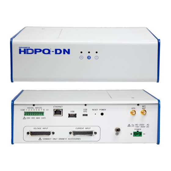
GETTING STARTED Connecting to Power Source Power The power supply inputs are rated 90–250 VAC 50/60 Specifications Hz and 100-300 VDC. A screw terminal block is used to connect up to #12 AWG gauge wire for the power input connections. The positive and negative inputs are fused internally and the fuses are not user- replaceable. - Page 9 The AC/DC power input is found at the rear panel of the unit. The rear panel for DataNode Model HDPQ-DN-MZP is shown below. Power Source The rear panel marking provides information about the input power rating.
-
Page 10: Controls, Indicators And Connectors
Controls, Indicators and Connectors Top View and Front View Top Panel The top panel shows the user replaceable Battery compartment. Internal Battery Sealed, rechargeable NiMH (Nickel Metal Hydride) cell The unit will always operate on the normal power source 50/60Hz, 90-250VAC or 100-300VDC. In the event of loss of power, the unit will seamlessly switch to the internal battery backup and will switch back to the normal power source when restored. - Page 11 Rear View This section describes the rear view panel of the HDPQ-DN-MZP. Digital Input (optional) – use to monitor on/off-type digital signals, such as breaker or switch position indicators. Ethernet Port – use to connect a wired Ethernet (RJ45) network.
-
Page 12: Reset To Factory Defaults
Default User name: admin Default Password: Dranetz Wired Ethernet IP address will be fixed at 192.168.0.30. NOTE: All saved data and setups will be lost when you reset the instrument settings to factory defaults. -
Page 13: Connecting To The Hdpq Datanode
The next sections describe how to connect to the HDPQ DataNode via: Wired Ethernet connection Wireless (WiFi) connection (available as an option) A proprietary Dranetz HDPQ IP Setup utility program if the IP Address is not known... -
Page 14: Connecting Via Wired Ethernet Connection
Enter the default User name: admin Enter the default Password: Dranetz User name and password are case sensitive, and must be entered as shown. When done entering the user name and password, click on the... - Page 15 Step Action The HDPQ DataNode Administrative Home Page will be displayed. Click the Commissioning Setup tab and select Ethernet Setup. Result: The following screen is displayed. On the Commissioning Setup - Ethernet Setup screen, enter the applicable setting changes and then click on the Submit Change button to connect to the instrument.
-
Page 16: Connecting Via Wireless (Wifi) Connection
Connecting via Wireless (WiFi) Connection The steps below show how to connect to the HDPQ DataNode via a Wireless (WiFi) connection. NOTE: The steps below can be done only if the WiFi option is installed and a WiFi antenna is connected to the rear panel of the HDPQ instrument. - Page 17 Step Action Disconnect from any network to which the instrument is currently connected by pressing the DISCONNECT button to the right. The instrument will attempt to connect to any “remembered” WiFi networks. To clear the list of “remembered” networks, click on CLEAR.
-
Page 18: Hdpq Ip Setup Program
HDPQ IP Setup Program A proprietary Dranetz setup utility program (HDPQIPSetup.exe) is designed to scan the local network to find and detect HDPQ DataNode units. This allows to you to discover HDPQ DataNodes on your network when you do not know the instrument’s IP address. The IP Setup program may be downloaded from the Dranetz website. - Page 19 Step Action Locate the MAC address of your HDPQ DataNode and click on that line in the HDPQ Device box. NOTE: A label on the HDPQ DataNode enclosure contains the MAC address. Click on the Get button to populate the left fields with your HDPQ Ethernet Settings.
- Page 20 Once the HDPQ DataNode is set up, connect to the instrument to verify the settings. NOTE: You may have to change the Internet settings on your computer to connect.
-
Page 21: Making Measurement Connections
MAKING MEASUREMENT CONNECTIONS WARNING Death, serious injury, or fire hazard could result from improper connection of this instrument. Read and understand the warnings in the beginning of this guide before connecting this instrument. ADVERTENCIA Una conexión incorrecta de este instrumento puede producir la muerte, lesiones graves y riesgo de incendio. -
Page 22: Connecting The Voltage And Current Input Pods
Pod Types Two (2) input pod types, voltage and current, are connected to the Voltage and Current pod inputs of DataNode Model HDPQ-DN-MZP. Connection is done on the rear panel using a 25-PIN interface cable connector. The pod inputs are attenuated to low voltage signals that can be measured by the DataNode. - Page 23 Pod Assembly Part Functions Parts Voltage pod (5536). Accepts four 5-600 Vrms (AC or DC), ±1000 Vpk channels A, B, C voltage, plus neutral and ground. Neutral to ground voltage range: 0.5 - 20 Vrms (AC or DC). Current pod (5537). Accepts four 0.01-5 Arms and up to #12 AWG wires.
-
Page 24: Connecting The Input Pods To The Hdpq Datanode
Connecting the Input Pods to the HDPQ DataNode... - Page 25 Use only fast blow type fuse which is rated 600V. Recommended fuse type is Littelfuse, part number KLKD.300 rated 600V AC/DC, 0.3A fast blow or Dranetz Fuse Voltage Adapter FVA- Do not replace fuse again if failure is repeated. WARNING Repeated failure indicates a defective condition that will not clear with replacement of the fuse.
-
Page 26: Single Phase
The figure also includes monitoring the Neutral to Ground voltage and Neutral currents. Neutral to ground measurements are important but optional. HDPQ-DN-MZP-101 CAUTION Connections must be performed in compliance with all safety requirements applicable to your installation. -
Page 27: Split Phase
The Neutral is chosen as the reference for measurement purposes. The figure also includes monitoring the Neutral to Ground voltage and Neutral currents. Neutral to ground measurements are important but optional. HDPQ-DN-MZP-102 CAUTION Connections must be performed in compliance with all safety requirements applicable to your installation. -
Page 28: Phase Four Wire Wye
The figure also includes monitoring the Neutral to Ground voltage and Neutral currents. Neutral to ground measurements are important but optional. HDPQ-DN-MZP-103 CAUTION Connections must be performed in compliance with all safety requirements applicable to your installation. -
Page 29: Phase (Floating Or Grounded) Delta
A monitoring phase A-B, channel B monitoring phase B-C, and channel C monitoring phase C-A. Current inputs are connected to measure line currents A, B, and C. HDPQ-DN-MZP-104 CAUTION Connections must be performed in compliance with all safety requirements applicable to your installation. -
Page 30: Phase 2-Watt Delta
B as the reference channel . The Source voltage and current inputs (A and C) are measured by the instrument using voltage and current inputs (A and B). HDPQ-DN-MZP-105 CAUTION Connections must be performed in compliance with all safety requirements applicable to your installation. -
Page 31: 1/2 Element Without Voltage Channel B
Channels A and C are connected to the voltage source. Channels A, B and C are connected to current sources. The neutral is connected to common and is the reference for the three channels. HDPQ-DN-MZP-106 CAUTION Connections must be performed in compliance with all safety requirements applicable to your installation. -
Page 32: 1/2 Element Without Voltage Channel C
Channels A and B are connected to the voltage source. Channels A, B and C are connected to current sources. The neutral is connected to common and is the reference for the three channels. HDPQ-DN-MZP-107 CAUTION Connections must be performed in compliance with all safety requirements applicable to your installation. -
Page 33: Accessories List
ACCESSORIES LIST Standard Accessories The following table lists the standard accessories for Dranetz HDPQ-DN- MZP. Qty. Description Part Number Terminal Block, 2 Position 902388-LF Use for the input power connector. HDPQ DataNode with Voltage/Current Pod QR-HDPQ-DN-MZP Connectors Quick Reference Guide... -
Page 34: Digital Inputs Hdpq-Dn-Mdin (Optional)
DIGITAL INPUTS HDPQ-DN-MDIN (optional) The factory-installed digital input option HDPQ-DN-MDIN is an eight channel, digital input module, providing users with the capability to monitor on/off-type digital signals, such as breaker or switch position indicators. A logical HI condition is when the voltage level goes above 3.0 volts and a logical LO condition is when the voltage level goes below 1.0 volts. - Page 35 Internal Supply Each channel 1 through 8 is referenced to the “COM” terminal. Individual channels can be connected between the “COM” to the “ – “ terminal of your monitoring source which serves as the reference. Each “+” terminal (1,2,3,4,5,6,7,8) of the instrument connects to the “+” terminal of your monitoring source.
-
Page 36: General Specifications
GENERAL SPECIFICATIONS Dimensions Size: 11” Width x 3.5” Height x 8.5” Depth 28cm x 9cm x 22cm Weight: 4.5 pounds Power Consumption 25 watts max Environmental Operating: 0 to +55 °C (32 to 131 °F) Storage: -40 to +70 °C (-40 to 158 °F) Humidity: 5% to 95% non-condensing Altitude... -
Page 37: Statements And Notices
User replaceable instrument batteries are warranted for a period of one year from the date of invoice. Certain Dranetz branded accessories, such as current transformers and other accessories not manufactured by... - Page 38 Dranetz, 1000 New Durham Road, Edison, New Jersey 08818. Copyright © 2019 Dranetz All Rights Reserved.
- Page 39 This page intentionally left blank.
Need help?
Do you have a question about the HDPQ-DN-MZP and is the answer not in the manual?
Questions and answers