
Related Manuals for CLIVET WSH-EE Series


Summary of Contents for CLIVET WSH-EE Series
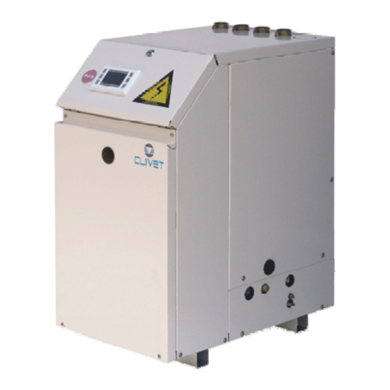
- Page 1 WSH-EE WSHH-EE 17-21-31-41-51-61-71-81-91-101-121 WATER COOLED WATER CHILLER FOR INDOOR INSTALLATION Installation and Use Manual M03Q40G6-03 21/11/07...
-
Page 3: Table Of Contents
U N I T I D E N T I F I C A T I O N ................4 I N S T R U C T I O N S F O R T H E U S E R . -
Page 4: Unit Identification
UNIT IDENTIFICATION SERIAL NUMBER LABEL The units are identified by the serial number label shown here. The label lists the type of unit (series and size), serial number, year of manufacture, number of electrical diagram, main technical data, logo and address of the manufacturer. The label is placed on the unit, generally near the electrical panel and also on the external panelling. -
Page 5: Instructions For The User
INSTRUCTIONS FOR THE USER • This is a partial sintex of the information provided in the manual; carefully read this manual • Carefully read this manual. Keep it with the electrical diagram. Make it available to technicians for servicing. • Ask the installer for training on start-up, shutdown, changing set points, placing in at-rest status, maintenance, what to do or not to do in the event of a breakdown. - Page 6 TO DO FOR: Some functions are active only if they are enabled during installation (remote ON-OFF, remote SUMMER WINTER change, remote ECO, sanitary hot water, set point compensation). Check with the installer about the configuration used. Start the unit LONG pressing of the ON/OFF button Choose the SUMMER mode “SUN”...
-
Page 7: Common Causes Of Shutdown
To reset the current alarm TEST + ON/OFF contemporary for some seconds ONLY AFTER THE CAUSE ELIMINATION ! Modify the HOT SANITARY water temperature* Control parameter Modify the water temp. in HEATING* Control parameter Only by SERVICE keypad Modify the water temp. in ECO HEATING* Control parameter Modify the water temp. -
Page 8: General Warnings
If the repairs are not performed, there will be a higher risk for things and peoples to become damaged Clivet products bear the CE mark, in compliance with the and injured. requirements of the following EC directives, including the FAULT –... -
Page 9: Residual Risks
RESIDUAL RISKS and precaution is taken when positioning and securing the GENERAL unit. This section lists some of the more common situations If the unit is easily accessible to children, unauthorized which, being beyond the control of the manufacturer, could persons or animals, this is a situation that can give rise be a source of risk to persons or property. - Page 10 Contact with parts that could become live when the unit is injured or suffer toxic effects. Always wear suitable clothing started up can result in electric shock, burns or death by and protective goggles when working in potential hazard electrocution. areas.
- Page 11 Check of the Personal protection. Assure adequate ventilation, especially in closed rooms. exposition / Control parameters. Difluorometan (R32): Recommended limits of exposition: AEL (8h and 12h TWA) = 1000 personal protection ml/m3 Pentafluoroetan (R125): Recommended limits of exposition: AEL (8h and 12h TWA) = 1000 ml/m3 Protection of respiratory tract.
-
Page 12: R E C E P T I O
RECEPTION INSPECTION UPON RECEPTION HANDLING Check on arrival that the unit has not suffered damage The operation of handling the unit must be carried out during transit and that it is complete in every part as respecting the instructions of the safety norms in force specified order. -
Page 13: P O S I T I O N I N
W1 , W2 , W3 etc . If more units are placed close to one another, the functional spaces must be doubled. On each anti-vibration device (if provided by CLIVET), its identifying code is stamped, for example C6100100 Flexible joints are necessary on all the hydraulic/... -
Page 14: W A T E R C O N N E C T I O N
WATER CONNECTIONS CONNECTIONS SUPPORTS GENERAL The weight of the hydraulic connections must be supported Piping must be designed with the least possible number of in the exterior of the unit so as not to stress the connections bends and head variations. If the pressure chute of the of user devices (exchangers, coils, humidifiers, etc ) . -
Page 15: Diagram Of Recommended Use Side Connection
DIAGRAM OF RECOMMENDED USE SIDE CONNECTION Depending on the type of machine and the selected setup, some components may be integrated into the unit. Charged system pressure switch vent pump expansion tank safety valve flow switch pressure switch / thermometer filter filling valve 10. -
Page 16: System Measures On Source Side
SYSTEM MEASURES ON SOURCE SIDE UNFREEZABLE LIQUIDS FILTER If the unit is used when the water temperature is lower than It is very important for the water to be free of impurities. If it + 4°C, avoid the formation of ice by using unfreezable is not, the efficiency of thermal exchange is diminished. - Page 17 MANAGEMENT OF SYSTEM ELEMENTS ON UTILITY SIDE The system can manage the following optionals. The diagrams are indicative: check the position of the water connections on the dimensional drawing of the unit or on the adhesive labels on the unit itself 3-way valve for sanitary hot water* double temperature - underfloor heating The valve is activated by external consent;...
-
Page 18: General
ELECTRICAL CONNECTION refer to standard units. In the event of differences between GENERAL the data of the registration plate and the data shown in this The characteristics of the electrical lines and relevant manual, as well as in the technical chart, please refer to the components must be determined by SPECIALIZED DATA SHOWN IN THE REGISTRATION PLATE. -
Page 19: Connection To The Mains
CONNECTION TO THE MAINS 1. Make sure that the sectioning device at the beginning of 6. Protect the cables, using the fairlead of an adequate the unit’s power line is opened, locked and equipped size. with a signal. 7. Using the layout of the electrical diagram, single out the 2. -
Page 20: Functional Connections
FUNCTIONAL CONNECTIONS FOR ALL THE CONNECTIONS MAKE REFERENCE TO THE ELECTRICAL PANEL SUPPLIED WITH UNIT Use voltage-free remote control devices that are suitable to commutate very low loads (12V, 10mA) Few inputs must be activated by configuration parameters whose access is reserved to authorized assistance centres (in order to avoid unauthorized modifications) remote ON / OFF remote SUMMER / WINTER *... - Page 21 ADDITIONAL HEATING ELEMENT * Allows to check the presence and correct phase sequence of the electrical power supply. It is supplied separately and must be assembled in the unit's electrical panel by the customer. T ext It is possible to control an external element for additional heating, typically electric heaters.
- Page 22 COUPLING WITH BOILER * Text This function allows the unit to be coupled to a boiler with "high temperature" thermostat setting (70 °C for example), i.e., with a out1 working point above the operating limits of the unit. The coupling to the boiler is managed using: •...
- Page 23 CONTROL OF THE 3-WAY VALVE FOR SANITARY HOT WATER * Sanitary hot water can be produced in summer and winter, based on an external request, by controlling a dedicated 3-way valve. When the contact is closed, the valve switches to the sanitary hot water storage and the unit changes its working set point to the sanitary hot water set point (par 117).
- Page 24 SANITARY HOT WATER: COMPENSATION OF THE SET POINT FOR EXTERNAL TEMPERATURE * The set point can be compensated according to the external temperature in 2 modes: hot season thermal efficiency curve when the external temperature is high, the sanitary hot water set point is decreased; in this manner the thermal efficiency is increased curve A in the graph the compensation is enabled in the standard configuration...
- Page 25 DUAL CONTROLS FOR TEMPERATURE – RADIANT PANELS It is necessary the expansion that must be fitted by the client (r refer to the kit instructions) and enabled by plug-in module parameter 140 = 1. With the optional kit, the mixed elements can be controlled: fan coils + radiant panels: •...
- Page 26 SET POINT COMPENSATION WITH 4-20 mA SIGNAL (WATER RESET) It optimizes the energetic efficiency of the unit by automatically changing the set-point according to an external signal of 4- 20 ma type. It requests the expansion plug-in module option that must be fitted by the client (refer to the kit instructions) and enabled by parameter 140 = 1.
- Page 27 INTERFACCIAMENTO UNITA’ VIA RS 485 Below the indications for the serial connection ; refer anyway to the CLIVET “RS 485 NETWORKS – GUIDELINES” document and ask for the COMMUNICATION PROTOCOL about the COMPACT electronics Couple of conductors twisted and shielded The total length of each single serial line, Section of conductor 0.22mm...
-
Page 28: S T A R T - U
START-UP ALL THE EQUIPMENT MUST BE COMMISSIONED BY AUTHORISED SERVICE CENTRES. THIS SERVICE IS LIMITED TO START-UP OF THE UNIT ONLY AND NOT THE CONNECTIONS OR INSTALLATION OF THE SYSTEM. ONLY QUALIFIED TECHNICIANS MUST PERFORM THE FOLLOWING OPERATIONS. PRELIMINARY CHECKS ELECTRICAL SYSTEM Before checking, please verify the following Check the proper tightening of the screws that fix the... -
Page 29: Verify Tensions - Absorptions
PERFORMANCE IN THE TECHNICAL BULLETIN referred VERIFY TENSIONS – ABSORPTIONS to various conditions of use. Check that the temperatures of the fluids are included in the Check for water side exchanger pressure drops: WORKING LIMITS. • Determine the water flow rate. If the controls of the previous paragraphs are positive, it is •... -
Page 30: C O N T R O
CONTROL The HEATING mode functions are active only on WSHH unit version . In WSH units, the relative parameters are VISIBLE but NOT ACTIVE , for example the winter setpoint. OPERING MODES Unit can be switched on and off by: •... -
Page 31: Set Point
SET-POINT COMPENSATIONS The compensations are evolved functions to protect the compressors and to adapt, as far as possible, the unit operating to the installation and use characteristics. The compensations prolong the compressor operating time and limit the start number; to do this they delay the compressor insertion point adding an offset. - Page 32 SECONDARY SET POINT – ECO A secondary set point can be used with different levels to the “normal” set point. It is normally set to give lower energy consumption with respect to the comfort setting: • The SECONDARY SUMMER set point is higher than the SUMMER setting. •...
-
Page 33: User Keypad
USER KEYPAD The keyboard allows visualizing and changing the functioning conditions of the unit. The service keyboard is needed to visualize or modify the functioning parameters. BUTTON FUNCTION COMFORT mode HEATING 1° set - point ECONOMIC mode COOLING 2° set-point ON / OFF LED operating LONG press... -
Page 34: Remote Or Service Keypad (Optionals)
ALARMS FLASHING LED: there is an anomaly at the AUTOMATIC reset FIXED LIGHT LED: there is an anomaly at the MANUAL reset ALARM RESET: TEST + ON/OFF keys pressed simultaneously for more than 2 seconds. Alarm type: REFRIGERANT CIRCUIT ELECTRICAL CIRCUIT ALARM WATER CIRCUIT ALARM ALARM Inlet probe... - Page 35 Limit of deactivation before reaching the antifreeze steps °C Sanitary water set point °C Configures remote inputs: 1 = H/C by keypad or supervisor Keypad address on Clivet Bus net: 7 =local; 1=remote PARAMETER MODIFICATION Select the Push SET button parameter...
- Page 36 UNIT STATA MENU INDICE DESCRIPTION VALUE Outdoor temperature °C 0-100% Outdoor Humidity Machine Clock – (only fed unit hours) Working hours C1 Pickups C1 Radiant panel valve status ON-OFF Radiant panel valve status Pump percentage Integration heater status ON-OFF Refreshing panel valve (Out-1) ON-OFF Radiant set Point °C...
- Page 37 Serial faulty - comunicazione tastiera / scheda base Auto. Faulty or disconnected water inlet probe Auto Faulty or disconnected water outlet probe Auto. Faulty or disconnected radiating panel water probe (radiating panel option) Auto. Faulty or disconnected coil probe Auto. Electric heater output probe Auto.
-
Page 38: R O U T I N E M A I N T E N A N C
ROUTINE MAINTENANCE BEFORE UNDERTAKING ANY SORT OF MAINTENANCE OR CLEANING, DISCONNECT THE ELECTRICAL POWER SUPPLY TO THE UNIT, AND ENSURE THAT OTHER PEOPLE CANNOT RE-CONNECT IT . All equipment is subjected to wear out. cleaning activities; otherwise, controls have performed by specialized technicians (INSPECTIONS). The maintenance makes : The machine should have a log book used to keep track of keeps the unit efficiency... -
Page 39: 97/23 Ce Ped Directive
97/23 CE PED DIRECTIVE 97/23 CE PED DIRECTIVE gives instructions for installers, Briefly and as an example, see the following : users and maintenance technicians as well. Refer to local COMPULSORY VERIFICATION OF THE FIRST actuation norms. INSTALLATION only for units assembled on the In Italy, refer to the Ministerial Decree of 1 December installer’s building site (for ex. - Page 40 R134a R407C R410A R134a R407C R410A Ts [°C] Ts [°C] Td [°C] Tb [°C] Ts [°C] Ts [°C] Ts [°C] Td [°C] Tb [°C] Ts [°C] -41.09 -26.36 -36.90 -43.90 -51.66 11.0 30.26 46.32 30.73 25.30 13.40 -37.14 -22.31 -33.11 -40.05 -48.02 11.2...
- Page 41 R134a R407C R410A R134a R407C R410A Ts [°C] Ts [°C] Td [°C] Tb [°C] Ts [°C] Ts [°C] Ts [°C] Td [°C] Tb [°C] Ts [°C] 22.0 57.53 73.74 56.00 51.63 37.88 33.0 76.22 92.30 72.94 69.73 54.54 22.2 57.92 74.14 56.36 52.01...
-
Page 42: T R O U B L E S H O O T I N
TROUBLESHOOTING THE OPERATIONS MUST BE CARRIED OUT BY TECHNICAL QUALIFIED PERSONNEL HAVING THE REQUISITES UNDER LAW REQUISITES AND IN CONFORMITY WITH THE SAFETY REGULATIONS IN FORCE. THE INTERVENTIONS WITHIN THE WARRANTY PERIOD WILL BE CARRIED OUT BY AUTHORIZED SERVICE CENTERS. BEFORE RESETTING AN ALARM, IDENTIFY AND ELIMINATE ITS CAUSE. - Page 43 LOW PRESSURE heating HIGH PRESSURE heating low water temperature (see operating limits) high air temperature (see operating limits) insufficient water flow to the exchanger (high fans do not work, direction of rotation inverted thermal difference between input and output) insufficient air flow to coil not CONSTANT flow (for example, if the pumps not CONSTANT flow (for example, if the pumps are turned off, certain areas of the plant are...
-
Page 44: D E C O M M I S S I O N I N G O F T H E U N I
DECOMMISSIONING OF THE UNIT DISCONNECTING THE UNIT DISMANTLING AND DISPOSAL The units must be disconnected by authorised personnel, THE UNIT MUST ALWAYS BE SENT TO AUTHORISED who before proceeding must first read the Residual Risks CENTRES FOR DISMANTLING AND DISPOSAL. section in this manual. -
Page 45: T E C H N I C A L D A T
TECHNICAL DATA Application: Terminal units SIZE Cooling Cooling capacity 1 kW 5,95 6,42 10,5 13,4 16,7 20,2 22,1 25,8 30,5 Compressor power input 1 kW 1,51 1,64 1,95 3,15 3,78 4,82 5,02 5,88 6,56 7,55 Total power input 2 kW 1,52 1,65 1,96... - Page 46 Applicaton: Unit for radiant panels Size Cooling Cooling capacity 1 kW 8,34 8,95 10,1 18,3 22,5 26,1 33,4 41,8 47,5 Compressor power input 1 kW 1,46 1,48 1,85 2,32 2,97 3,94 4,97 5,09 5,99 6,64 7,95 Total power input 2 kW 1,47 1,49 1,86...
- Page 47 OPERATINE LIMITS (COOLING) SIZE EXSTERNAL EXCHANGER Min. water inlet temperature °C Min. water inlet temperature °C Max water outlet temperature °C Min. water outlet temperature °C Water thermal head (min / max) °C 5/16 INTERNAL EXCHANGER Max water inlet temperature °C Max water outlet temperature °C...
-
Page 48: Dimensions
DIMENSIONS Size 17-51 119.5 119.5 (15) "G" 119.5 119.5 (1) COMPRESSOR SIZE (2) INTERNAL EXCHANGER = UTILITY SIDE EXCHANGER (3) EXTERNAL EXCHANGER = SOURCE SIDE EXCHANGER (4) ELECTRICAL PANEL (5) INTERNAL EXCHANGER WATER INLET (6) INTERNAL EXCHANGER WATER OUTLET Length (7) EXTERNAL EXCHANGER WATER INLET Depth (8) EXTERNAL EXCHANGER WATER OUTLET... - Page 49 Size 61-121 (15) "G" 107.5 127.5 (1) COMPRESSOR SIZE 101 121 (2) INTERNAL EXCHANGER = UTILITY SIDE EXCHANGER 152 165 173 174 175 182 (3) EXTERNAL EXCHANGER = SOURCE SIDE EXCHANGER 215 202 197 193 192 185 (4) ELECTRICAL PANEL 285 300 330 333 336 331 (5) INTERNAL EXCHANGER WATER INLET 228 213 186 180 177 182...
- Page 52 Fax + 33 (0)1 69 20 60 76 info.de@clivet.com info@clivettfa.com info.fr@clivet.com The data contained in this bulletin is not binding and may be changed by the manufacturer without prior notice. All reproduction, even partial, is PROHIBITED. © COPYRIGHT - CLIVET S.P.A. - FELTRE (BL) - ITALIA...
Need help?
Do you have a question about the WSH-EE Series and is the answer not in the manual?
Questions and answers