Table of Contents
Advertisement
Quick Links
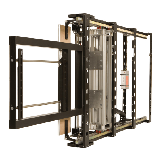
Installation Instructions
HL - Horizontal Lift Mechanism
Design Highlights
-Unique Drop and Roll Flap Mechanism
-Hand Made Quality Construction
-Full Cable Management
-Custom Sized to Suit Exact Size of Screen
-Range of Add On Functions Available
-Custom Frames for Deeper Screens and Speakers
-Positively Driven Rack System for Secure and Robust Lifting
Thank you for choosing
futureautomation
email info@futureautomation.co.uk tel: +44 (0) 1438 833577 fax: +44 (0) 1438 833565
ISSUE 001
Advertisement
Table of Contents

Related Manuals for Future Automation HL


Summary of Contents for Future Automation HL
- Page 1 Installation Instructions HL - Horizontal Lift Mechanism Design Highlights -Unique Drop and Roll Flap Mechanism -Hand Made Quality Construction -Full Cable Management -Custom Sized to Suit Exact Size of Screen -Range of Add On Functions Available -Custom Frames for Deeper Screens and Speakers...
-
Page 2: Safety Information
Exceeding the weight capacity can result in serious personal injury or damage to equipment. Future Sound & Vision trading as Future Automation intend to make this and all documentation as accurate as possible. However, Future Automation makes no claim that the information contained herein covers all details, conditions or variations, nor does it provide for every possible contingency in connection with the installation or use of this product. -
Page 3: Table Of Contents
HL - Horizontal Lift Mechanism Contents Page Introduction Safety Information Contents Contents Tool Indicator Icons Installation Parts List Package Contents Stage 1 Before You Start Stage 2 Fitting Flap Panel to the Mechanism Stage 3 Fixing the Lift to the Cabinet... -
Page 4: Contents
Any damage to products during transit that is not checked and notified as “unchecked” or “damaged” upon receipt of delivery. Any part of your system that needs to be replaced during a warranty repair becomes the property of Future Automation. -
Page 5: Package Contents
HL - Horizontal Lift Mechanism Package Contents Nuts & Bolts Multipack: A range of nuts, bolts, washers 1 - Mechanism and spacers to help add in the 1.1 - Flap mounting for your screen 1.2 - Screen Mount 1.3 - Cable Management 1.4 - Lifting Beam... -
Page 6: Before You Start
HL - Horizontal Lift Mechanism Before you Start Check the Operation of the Mechanism. Firstly, remove all the red cable ties which keep the mechanism safe and secure during transit. There are usually 6 ties in the locations circled on the image. -
Page 7: Fitting Flap Panel To The Mechanism
Make sure the base panel lines up squarely, directly on top of the lifting beam. Consult HL TECHNICAL SHEET before fabricating any flaps or base panels. Screw base in place from underside through the 2 fixing brackets on either side. -
Page 8: Fixing The Lift To The Cabinet
HL - Horizontal Lift Mechanism Fixing the Lift to the Cabinet Place the mechanism within the cabinet / wall. Run the beam to the IN position and carefully guide the base through the opening. With the opening side of the mechanism... -
Page 9: Adjusting The Out Stop Position
HL - Horizontal Lift Mechanism Adjusting the Out Stop Position By adjusting the screw up or down, you can adjust the out position of the lifting beam and also, the base infill panel. Make sure that the gears and racks are evenly greased and move smoothly. -
Page 10: Positioning The Base Infill Panel
HL - Horizontal Lift Mechanism Positioning the Base Infill Panel There should be a gap of about 3mm [1/8”] around the edges of the base panel to the cabinet opening. Page 9 of 20 // email info@futureautomation.co.uk tel: +44 (0) 1438 833577 fax: +44 (0) 1438 833565... -
Page 11: Adjusting The Flap Closed Position
HL - Horizontal Lift Mechanism Adjusting the Flap Closed Position 1. - By adjusting the white screw, at each side of the lift, you can adjust the tilt of the flap. 2. - By loosening the M6 bolts on each side under the flap, you can adjust the position of the flap in the cabinet top. -
Page 12: Adjusting The Flap Open Position
HL - Horizontal Lift Mechanism Adjusting the Open Position By adjusting the bolts on each flap arm, it is possible to alter the angle the flap opens to. It is very important that when the flap is open, it rests in a horizontal position, as shown to the left. -
Page 13: Checking Screen Mount Suitability
HL - Horizontal Lift Mechanism Checking Screen Mount Suitability With a standard horizontal lift, the supplied mounting type will be able to accommodate VESA 200, 300 or 400 mount patterns. Check the screen is compatible with these VESA patterns. VESA 400... -
Page 14: Mounting The Screen To The Lift
HL - Horizontal Lift Mechanism Mounting the Screen to the Lift Before mounting any screen, press STOP on the IR remote in order to prevent any motor movements during the mounting procedure. Trim Panels Lock Mount Toggles Mount Plate Rear Cover Simply mount the screen on to the mount supplied with your mechanism. -
Page 15: Running The Mechanism
HL - Horizontal Lift Mechanism Fix the IR Sensor, Screen Mounting & Running the Mechanism The IR sensor can be located anywhere outside of the cabinet. It is very important that once the mechanism is set up, the lift is run in and out a number of times to bed in and stabilise. -
Page 16: Contact Closure
HL - Horizontal Lift Mechanism Contact Closure - Use an RJ45 connector in the CCI socket on the control box to operate via contact closure WIRE / CABLE CONTACT CLOSURE DESCRIPTION ACTION 568A 568B LED INDICATOR 12V SUPPLY 12V SUPPLY - CURRENT LIMITED When 12V attached, device will go OUT. -
Page 17: Rs232 Controls
HL - Horizontal Lift Mechanism RS232 - Use an RJ25 connector in the socket marked RS232 on the control box to operate using RS232 Pin 1: RX Pin 6 : TX Pin 2: TX Pin 3 & 4: GROUND Pin 3: RX... -
Page 18: Ir Control
HL - Horizontal Lift Mechanism Operation buttons for the IR remote In - Brings the mechanism Out - Brings the inside the cabinet mechanism out of the cabinet facing forward Stop - Will stop the operation at any position Note Only buttons indicated are functional with the product. - Page 19 HL - Horizontal Lift Mechanism Horizontal Lift Mechanism - Trouble shooting guide Lift Mechanism HL - Trouble shooting For information on our products please refer to our web site - www.futureautomation.co.uk or for questions on installations and our product range please...
- Page 20 HL - Horizontal Lift Mechanism Technical Overview A general technical overview of the HL lift mechanism Product Dimensions Custom Weight Custom Power Consumption 250W - 500W Power Consumption 100mA Standby Lifting Capacity (Kg) 50Kg [110.2lb] Standard Screen Mount Colour Black...
- Page 21 HL - Horizontal Lift Mechanism Notes... Page 20 of 20 // email info@futureautomation.co.uk tel: +44 (0) 1438 833577 fax: +44 (0) 1438 833565...
- Page 22 Future Automation Unit 2 Kimpton Enterprise Park Claggy Road Kimpton Hertfordshire SG4 8HP United Kingdom Tel: +44 (0) 1438 833 577 Fax: +44 (0) 1438 833 565 Email: info@futureautomation.co.uk www.futureautomation.co.uk...
Need help?
Do you have a question about the HL and is the answer not in the manual?
Questions and answers