Table of Contents
Advertisement
Quick Links
İMALATÇI FİRMA
ADRES
TELEFON
TELEFAX
İMZA-KAŞE
ÜRÜNÜN CİNSİ
MARKASI
MODEL KODU
BANDROL/SERİ NO
TESLİM TARİHİ
GARANTİ SÜRESİ
AZAMİ TAMİR SÜRESİ
YETKİLİ SATICI FİRMA
ADRES
TELEFON
TELEFAX
İMZA-KAŞE
GARANTİ BELGESİ
:
YILMAZ MAKİNE SANAYİ VE TİCARET A.Ş
:
TAŞDELEN MH. ATABEY CD. No 9 34788 ÇEKMEKÖY
İSTANBUL-TÜRKİYE
:
0216.312.28.28 PBX
:
0216.484.42.88
:
:
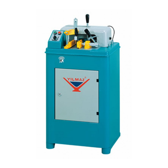
ALÜMİNYUM ve PVC ORTAKAYIT ALIŞTIRMA FREZE MAKİNESİ
:
YILMAZ
:
KM 210 – KM 211
:
:
:
1 YIL
:
30 İŞ GÜNÜ
:
:
:
:
:
1
Advertisement
Table of Contents

Subscribe to Our Youtube Channel
Related Manuals for YILMAZ KM 210


Summary of Contents for YILMAZ KM 210
- Page 1 GARANTİ BELGESİ İMALATÇI FİRMA YILMAZ MAKİNE SANAYİ VE TİCARET A.Ş ADRES TAŞDELEN MH. ATABEY CD. No 9 34788 ÇEKMEKÖY İSTANBUL-TÜRKİYE TELEFON 0216.312.28.28 PBX TELEFAX 0216.484.42.88 İMZA-KAŞE ÜRÜNÜN CİNSİ ALÜMİNYUM ve PVC ORTAKAYIT ALIŞTIRMA FREZE MAKİNESİ MARKASI YILMAZ MODEL KODU KM 210 – KM 211 BANDROL/SERİ...
- Page 2 TEKNİK ÖZELLİKLER - TECHNICAL FEATURES - ТЕХНИЧЕСКИЕ ОСОБЕННОСТИ KM 210 3000 W = 58 D = max.160 800 W 50 Hz 1200 W 50 Hz D/dak. L = 46 230 V AC P N PE 400 V AC 3P PE...
- Page 4 BOYUTLAR – DIMENSIONS – РАЗМЕРЫ RESİM-FIGURE-РИСУНОК 1...
- Page 5 PARÇA LİSTESİ - PART LIST - ПЕРЕЧЕНЬ ДЕТАЛЕЙ RESİM-FIGURE-РИСУНОК 3 RESİM-FIGURE-РИСУНОК 2...
- Page 6 RESİM-FIGURE-РИСУНОК 5 RESİM-FIGURE-РИСУНОК 4 RESİM-FIGURE-РИСУНОК 7 RESİM-FIGURE-РИСУНОК 6...
- Page 7 RESİM-FIGURE-РИСУНОК 8...
- Page 8 STOK KODU ADET STOK KODU ADET STOCK CODE STOCK CODE номер номер ПОРЯДОК КОД КОЛИЧЕСТВО ПОРЯДОК КОД КОЛИЧЕСТВО 1SA010000-0007 3UA060030-0005 1SC170000-0001 3UA040030-0005 3UA110030-0020 * 2TU012610-0054 * 1PN080000-0009 * 3UA060030-0004 * 1PN010000-0087* 3UA040030-0002 2TU012510-0096 2TU011110-0091 1SA030000-0003 1PL010000-0016 1PL010000-0020 ** 2TU012510-0191 2TU012510-0100 3UA370030-0003 2TU012610-0031 2TU012610-0009...
-
Page 9: Table Of Contents
ENGLISH CONTENTS 1. General information 1.1. Introduction 1.2. Service Information 2. Safety 2.1. Safety Symbols and Their Meanings 2.2. Accidents Prevention 2.3. General Safety Information 3. Machine’s Description 4. Transport of the Machine 5. Installation of the Machine 5.1. Preparation 5.2. -
Page 10: General Information
The technical drawings and details contained in this manual constitute a guide for the operator. 1.2. Service Information In case of any technical problem please contact your nearest YILMAZ dealer, or YILMAZ head office through the above mentioned phone, fax or e-mail address. - Page 11 AUTHORIZED TECHNICAL SERVICE CENTER ADDRESS TAŞDELEN MH. ATABEY CD. No 9 34788 ÇEKMEKÖY – İSTANBUL / TÜRKİYE 0216 312 28 28 Pbx. 0216 484 42 88 E-mail service@yilmazmachine.com.tr www.yilmazmachine.com.tr For minimize the documantation, It is wery necessary to mention below details at the agreements signed with suppliers and dealers of the purchased machines ...
-
Page 12: Safety
2. SAFETY 2.1. Safety Symbols and Their Meanings Ensure safe working position, always keep your Read the user guide balance. Wear ear protectors Elektrical excitation Wear safety goggles Don’t place your hands between parts in motion.. If the power cable should be damaged during operation, don't touch and unplug it. -
Page 13: Accidents Prevention
2.2. Accidents Prevention 2.2.1 Our machines are manufactured in accordance with CE safety directives, which cover national and international safety directives. 2.2.2 It is the task of the employer to warn his staff against accident risks, to train them on prevention of accidents, to provide for necessary safety equipment and devices for the operator’s safety. - Page 14 2.3.4 Use correct illumination for the safety of the operator. ( ISO 8995-89 Standard The lighting of indoor work system) 2.3.5 Don’t use any materials other than those recommended by the manufacturer for cutting operations on the machine. 2.3.6 Ensure that the work piece is clamped appropriately by the machine's clamp or vice 2.3.7 Ensure safe working position, always keep your balance.
-
Page 15: Machine's Description
3. MACHINE’S DESCRIPTION End milling machines are designed for precise end milling operations in PVC and Aluminium profiles. Portable endmilling machine. The machine has been designed in accordance with the CE Directives. Clamping and milling operation is manual. STANDART AKSESUARLAR OPSİYONEL AKSESUARLAR Service keys... -
Page 16: Installation Of The Machine
5. INSTALLATION OF THE MACHINE 5.1 Preparation 5.1.1 The machine size and weight measurements, given the technical specification sheet.The ground, where the machine will be placed, should be even, solid enough to bear the weight of the machine. 5.1.2 The machine should be located approx. 100 cm away from the rear wall. The power connection plug of the machine is located on the rear side of the machine. -
Page 17: Machine's Safety Information
6. MACHINE’S SAFETY INFORMATION 6.1 Lifting, installation, electric maintenance of the machine should be carried out by qualified personnel only. 6.2 Routine maintenance and scheduled maintenance should be carried out by qualified personnel after unplugging machine and disconnecting the air supply first. 6.3 Ensure that the machine has been cleaned, tested and maintain before starting to operate. -
Page 18: Operation
7.1.2 Clean all surfaces of the machine from chip and foreign particles. Use eye glasses for protection. 7.1.3 Our portable end milling machine KM 210-211 is used for working of non-ferrous materials, aluminum and PVC mullion profiles to make <T > connections. -
Page 19: Maintenance, Service And Repair
7.2.5 Release the clamps and take out the end milled profile. The milling operation has always to be started from the starting position of the machine. Never start this operation from the opposite side. NOTE:The milling cutters have to be started freely, without touching the profile. They have to start to rotate first before making the milling operation. -
Page 20: Changing The Cutting Tool
8.2 Changing the cutting tool 8.2.1 Use protective gloves when replacing cutting tool. 8.2.2 Cut the electric connection of the machine. 8.2.3 Open the upper protection cover. (FIGURE 2-NO: 7) 8.2.4 With the help of 6 Allen key (given with the machine), demount the bolt (FIGURE 8-NO: 31) from its location.. Take the washer (FIGURE 8-NO: 32) and the exterior coupling (FIGURE 8-NO: 33) to the outside.. -
Page 21: Adjust The Air Pressure (Pneumatic Systems)
Adjust the air pressure (pneumatic systems) 8.3.1 Pull up pressure adjustment valve. Set adjustment valve to the desired value on manometer by turning it clockwise or counter clockwise. Then lock the valve by pressing it down. 8.3.2 Set the air pressure between 6 and 8 BAR. If air pressure drops below the stated values, accessories operating with pneumatic power do not work. -
Page 22: Warranty Conditions
9. WARRANTY CONDITIONS YILMAZ Machine Industry and Trade Limited Company, guarantees that all machines have been tested and conform to the international standards. The guarantee is valid 24 months from despatch date and does not cover the electrical parts of the machine. - Page 23 ELECTRIC&PNEUMATIC DİAGRAM...
- Page 24 3P ELECTRICAL DIAGRAM...
- Page 25 1P ELECTRICAL DIAGRAM...
- Page 26 PNEUMATIC DIAGRAM...
Need help?
Do you have a question about the KM 210 and is the answer not in the manual?
Questions and answers