Advertisement
Table of Contents
Product End-of-Life Disassembly Instructions
Product Category: External Options
Marketing Name / Model
[List multiple models if applicable.]
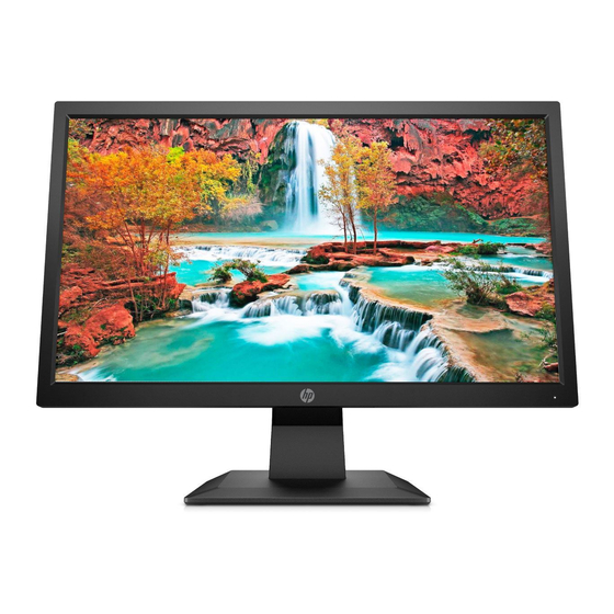
HP P204v 19.5-inch Monitor
Purpose: The document is intended for use by end-of-life recyclers or treatment facilities. It provides the basic instructions for the
disassembly of HPI products to remove components and materials requiring selective treatment, as defined by EU directive
2012/19/EC, Waste Electrical and Electronic Equipment (WEEE).
NOTE: Recyclers should sort plastic materials into resin streams for recycling based on the ISO 11469 plastic marking code on the
plastic part. For any questions on plastic marking, please contact
1.0 Items Requiring Selective Treatment
1.1 Items listed below are classified as requiring selective treatment.
1.2 Enter the quantity of items contained within the product which require selective treatment in the right column, as applicable.
Item Description
Printed Circuit Boards (PCB) or Printed Circuit
Assemblies (PCA)
Batteries, excluding Li-Ion batteries.
Li-Ion batteries. Include all Li-Ion batteries if more than
one is provided with the product (such as a detachable
notebook keyboard battery, RTC coin cell, etc.)
Mercury-containing components
Liquid Crystal Displays (LCD) with a surface greater than
100 sq cm
Cathode Ray Tubes (CRT)
Capacitors / condensers (Containing PCB/PCT)
Electrolytic Capacitors / Condensers measuring greater
than 2.5 cm in diameter or height
External electrical cables and cords
Gas Discharge Lamps
Plastics containing Brominated Flame Retardants
weighing > 25 grams (not including PCBs or PCAs
already listed as a separate item above)
EL-MF877-00
Template Revision C
Last revalidation date 09-May-2018
Notes
With a surface greater than 10 sq cm
IF board*1,KP board*1,Power board*1
All types including standard alkaline, coin or button style
batteries
Battery(ies) are attached to the product by (check all
that apply with an "x" inside the "[ ]"):
[
[
[
[
NOTE: Add detailed removal procedures including
required tools in the sections 3.1 and 3.2.
For example, mercury in lamps, display backlights,
scanner lamps, switches, batteries
Includes background illuminated displays with gas
discharge lamps panel*1
VGA cable*1, HDMI*1,Power cord*1
HPI instructions for this template are available at
HP's Sustainability
Contact.
] screws
] snaps
] adhesive
] other. Explain
EL-MF877-01
Quantity of
items
included in
product
3
0
0
0
1
0
0
0
3
0
0
Page 1
Advertisement
Table of Contents

Related Manuals for HP P204v


Summary of Contents for HP P204v
- Page 1 Marketing Name / Model [List multiple models if applicable.] HP P204v 19.5-inch Monitor Purpose: The document is intended for use by end-of-life recyclers or treatment facilities. It provides the basic instructions for the disassembly of HPI products to remove components and materials requiring selective treatment, as defined by EU directive 2012/19/EC, Waste Electrical and Electronic Equipment (WEEE).
- Page 2 Quantity of items Item Description Notes included in product Components and parts containing toner and ink, Include the cartridges, print heads, tubes, vent including liquids, semi-liquids (gel/paste) and toner chambers, and service stations. Components and waste containing asbestos Components, parts and materials containing refractory ceramic fibers Components, parts and materials containing radioactive substances...
- Page 3 Step 2. Push the Quick Release Button with one finger or stick, Step 1. Lay the display on a soft surface, hang on the stand. the another hand pull the stand out at same time. Step 4. Unscrew 4 VESA screws (M4*10). Step 3.
- Page 4 Step 6. Separate Bucket from Bezel slightly, DO NOT move Step 5. Unhook Bucket and Bezel with a repair tool, suggested Bucket away directly. sequence is from repair slot as picture show in a counterclockwise direction. Step 8. Peel off the cable from Bucket. Step 7.
- Page 5 Step 10. Take out keypad from right side. Step 9. Unscrew 2 screws (T2*4). Step 12. Disconnect the terminals. Step 11. Peel off all Al foils and Tapes.
- Page 6 Step 14. The Rubber is detachable. Step 13. Take out Chassis and Panel. Step 16. Unscrew 5 pan screws (M3*6), 1 GND screw (M4*9) Step 15. Take away the mylar. and 2 bolts.
- Page 7 Step 18. Disconnect the terminals. Step 17. Take out Power and IF board. Step 20. Peel off the mylars. Step 19. Power and IF board as picture show.
Need help?
Do you have a question about the P204v and is the answer not in the manual?
Questions and answers