Table of Contents
Advertisement
Quick Links
Advertisement
Table of Contents

Related Manuals for Shuttle XPC SD31P


Summary of Contents for Shuttle XPC SD31P
- Page 1 XPC User Guide For the : SD31P...
- Page 2 Shuttle Mainboard EMI Test Statement Shuttle mainboards have been through EMI tests according to the following series of regulations: EN55022/CISPR22/AS/NZS3548 Class B, EN55024 (1998/AS/NZS), EN4252.1 (1994), EN61000, ANSI C63.4 (1992), CFR47 Part 15 Subpart B, and CNS13438 (1997). The items tested are illustrated as follows: (A) Voltage: AC 110V/60HZ &...
- Page 3 Memory x2 A-Data 430F3H4TR/DDR2/533, 512MB Power Shuttle PC43I3503, 350W (E) Notices for Assembling Computers: 1. An I/O shielding should be contacted with I/O metallic parts of a mainboard. 2. Cables should appropriately be arranged and fixed in a case. Follow instructions: Ø...
- Page 4 2. This device must accept any interference received, including interference that may cause undesired operation. Trademarks Shuttle is a registered trademark of Shuttle Inc. Intel and Pentium are registered trademarks of Intel Corporation. PS/2 is a registered trademark of IBM Corporation.
- Page 5 Read the following precautions before setting up a Shuttle XPC. CAUTION Incorrectly replacing the battery may damage this computer. Replace only with the same or equivalent as recommended by Shuttle. Dispose of used batteries according to the manufacturer's instructions. Installation Notices Do not place this device underneath heavy loads or in an unstable position.
-
Page 6: Table Of Contents
TABLE OF CONTENTS 1 Function Introduction ..................1 1.1 XPC Introduction ................... 1 1.2 Model Specifications ..................2 1.3 XPC Exterior Dissection ................3 1.3.1 XPC Front ..................... 3 1.3.2 XPC Back ..................... 4 1.4 Accessories ....................5 1.5 Hardware Installation ..................6 1.5.1 FD31 mainboard illustration .............. - Page 7 2.3 Peripheral Installation ................23 2.3.1 FDD Cable and Rack Mounting ............23 2.3.2 HDD Rack Mounting ................25 2.3.3 Optical Drive Rack Mounting ..............26 2.3.4 Install the Rack Peripherals ..............27 2.3.5 Install more Serial ATA HDDs ............... 31 2.4 Accessories Installation ................
- Page 8 Frequency/Voltage Control ................66 LOAD FAIL-SAFE DEFAULTS ..............68 LOAD OPTIMIZED DEFAULTS ..............68 SET PASSWORD ..................69 SAVE & EXIT SETUP .................. 70 EXIT WITHOUT SAVING ................70...
-
Page 9: Function Introduction
The XPC has been designed to be easily assembled and configured directly by the end user. Consumers can choose to buy preconfigured, ready-to-run XPC’ s as well~a list of Shuttle-authorized value-added resellers can be found at www. shuttle.com. -
Page 10: Model Specifications
< 1.2 Model Specifications Form Factor Shuttle Small Form Factor Processor 533/800/1066 MHz FSB Intel Pentium 4 (LGA775) Chipset Intel 945G + ICH7R Memory 240 pins 533/667 DDR2 DIMM X2 with Single & Dual-Channel Mode configuration Supports 256Mb,512Mb, and 1Gb technologies for X8 and X16 devices Audio H/W Audio Creative P17 (7.1-CHANNEL) -
Page 11: Xpc Exterior Dissection
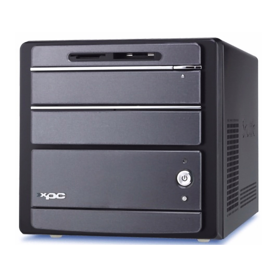
< 1.3 XPC Exterior Dissection Note : Shuttle offers a variety of different XPC models loaded with various options. The illustration below will help familarize you with the included features in your new XPC. < 1.3.1 XPC Front 1. Card R/W (MS, MS Pro, MMC, SD, SM) 2. -
Page 12: Xpc Back
< 1.3.2 XPC Back FireWire® 400 port Clear CMOS button AC power switch AC power socket COM port VGA port 11 13 PS/2 Mouse PS/2 Keyboard LAN port USB ports Serial ATA port SPDIF OUT SATA (Coaxial) SPDIF OUT (Optical) Central/Bass Side Surr (R/L) SPDIF IN (Optical) -
Page 13: Accessories
13. Shuttle Extras CD (1) 14. Motherboard CD Driver (32bits/64bits) (2) 15. XPC user guide (1) 16. RAID manual (1) Note : Bundled Accessories may differ from specified. If there are items missing, please contact your local authorized Shuttle dealer. -
Page 14: Hardware Installation
< 1.5 XPC Mainboard < 1.5.1 FD31 mainboard illustration Giga LAN (GbE) & USB 2.0 Port PS/2 Keyboard/Mouse Port USB 2.0 & SATA Ports Wireless KB/MS Header- JP8 SPDIF-OUT RCA Coaxial/Optical Ports COM & VGA Port SPDIF-IN Optical/ Surround/ Center/Bass/ Front-Out/ Surround-Back/ Line-In Ports System Power Connector- ATX2 EXT. -
Page 15: Jumper Settings
< 1.5.2 Jumper Settings Front Panel Connector (JP7) Header JP7 can be used to provide operation status signals to the front daughterboard. Note that this is an alternative header to the 50pin streamline header that also con- nects the motherboard to the front daughterboard. Pin Assignments (JP7): 1=HDLED_PU 2=GLEDA... -
Page 16: Front Panel Audio/Usb/1394 Connector (Jp6/Jp3)
Front Panel AUDIO/ USB/ 1394 Connector (JP6/JP3) Headers JP6 and JP3 are used to connect cables to front panel connectors mounted on front-panel or back-panel. The front panel is where the hard drive activity lights, reset button, on/off button, computer power on light, USB connectors, 1394 connectors, and audio headers, are located. -
Page 17: Line-In (Cn2)(Blue), Aux-In (Cn3)(White) Connectors
LINE-IN (CN2)(Blue), AUX-IN (CN3)(White) Connectors Port CN2(Blue) and CN3(White) are used to connect stereo audio inputs from a CD-ROM. Pin Assignments (CN2): 1=Line-in Left 2=Line-GND 3= Line-GND 4=Line-in Right Pin Assignments (CN3): 1=AUX-in Left 2=AUX-GND 3= AUX-GND 4=AUX-in Right Wireless Keyboard and Mouse Connectors (JP8) JP8 header provides support for a wireless keyboard and mouse. -
Page 18: Ext.gpi Header (Jp1)
EXT. GPI Header (JP1) The GPI supports user-defined function names. This means that the functions inside the platform-independent code can be called anything. The user defines the linking function names in the GPI header file. Pin Assignments (JP1): 1=5VSB 2=KEY 3=GND 1 2 3 4 5 4=GPI8... -
Page 19: Usb Header (Usb3)
A DB25 male parallel port header is located near the rear panel of the mainboard. The header is used to connect a parallel port socket (PC15) to the mainboard. The parallel printer port can be purchased from Shuttle as an optional accessory. Pin Assignments (JP5):... -
Page 20: Xpc Installation Guide
2 XPC Installation Guide < 2.1 Installation Note : For safety reasons, please ensure that the power cord is disconnected before opening the case. < 2.1.1 Remove the Cover 1. Unscrew the four thumbscrews. 2. Slide the cover backwards and upwards. -
Page 21: Remove The Rack
< 2.1.2 Remove the Rack 1. Unbuckle the two Serial ATA HDD mounting brackets from the rack. Serial ATA HDD mounting brackets 2. Remove the rack. -
Page 22: Cpu, Ddr2 And Ice Installation
< 2.2 CPU, DDR2 and ICE Installation < 2.2.1 Remove the ICE Module 1. Gently lift and remove the fan duct. Fan duct 2. Unplug the fan power connector. 3. Unfasten the four ICE module attachment screws. - Page 23 4. Remove the ICE module from the chassis and put it aside. ICE Heat-Pipe Module Heat-pipe Smart Fan Smart Fan Power Connector...
-
Page 24: Install The Cpu
< 2.2.2 Install the CPU 1. Unfasten the two smart fan screws. 2. Swing the fan out to allow easyaccess to the CPU socket and RAM dimms. 3. Remove the protective cover. Note : This 775 pin socket is fragile and easily damaged. Always use extreme care when installing a CPU and limit the number of times that you remove or change the CPU. - Page 25 4. First unlock and raise the socket lever, then open the load plate (be careful not to touch the socket pins during this process). Unlock the lever Lift the CPU socket lever 5. Orientate the CPU and socket, aligning the yellow triangle on the corner of the CPU with the triangle on the socket.
- Page 26 6. Close the load plate, lower the CPU socket lever and lock in place. 7. Spread an even layer of thermal compound on the CPU die. Thermal compound application area...
-
Page 27: Ddr2 Installation
< 2.2.3 DDR2 Installation Memory Configuration : Install memory in any or all of the banks according to the combinations shown below. The 945 G/P only support DDR2 533 4-4-4 and DDR2 667 5-5-5 timings. TOTAL 2 DIMM in Single or Dual Channel Mode up to 2GB and 1GB per DIMM Density 256 Mbit... - Page 28 2. Align the DDR2 module's cutout with the DIMM slot notch. Slide the DDR2 module into the DIMM slot. Cutout Notch Latch Latch 3. Check that the latches are closed, and the DDR2 module is firmly installed. 4. Return the fan to the original position and secure.
-
Page 29: Install The Ice Module
< 2.2.4 Install the ICE Module 1. Place the ICE module on top of the CPU die and match the screws with the holes on the motherboard. 2. Screw the ICE module to the motherboard. Note to press down on the opposite diagonal corner while tightening each screw. - Page 30 4. Reattach the fan duct to the six attachment points as shown below. Fan duct Note : The fan duct must be installed to efficiently deliver cool air directly to the ICE module.
-
Page 31: Peripheral Installation
< 2.3 Peripheral Installation This XPC introduces a revolutionary new way of installing peripherals. This completely TOOLLESS installation is quick and simple, but first take a moment to orientate yourself with the rack and mounting brackets. Note : The rack is designed for one 3.5" device only. If you are installing a FDD, proceed to step 2.3.1;... - Page 32 3. Slide the FDD into the rack until the ends of the mounting brackets are secured under the attachment points as shown. 4. Attach the FDD signal cable and power cable. FDD Power extension cable Pin1 (white Line) FDD Installation FDD Cable...
-
Page 33: Hdd Rack Mounting
< 2.3.2 HDD Rack Mounting 1. Take the two HDD mounting brackets HDD mounting brackets from the accessory box. 2. Align the bracket pins with the HDD and attach. Note : The mounting brackets are side specific. 3. Slide the HDD into the rack until the ends of the mounting brackets are secured under the attachment points as shown. -
Page 34: Optical Drive Rack Mounting
< 2.3.3 Optical Drive Rack Mounting 1. Take the two optical drive mounting brackets. Optical drive mounting brackets 2. Align the pins on the mounting brackets with the holes on the optical drive and attach. Note : The mounting brackets are side specific. -
Page 35: Install The Rack Peripherals
4. Jumper settings. If you are using an IDE HDD, you will need to set the jumpers on the HDD to master and the optical drive to slave. Refer to your peripherals for details on jumper positioning. Optical Drive jumper IDE HDD jumper <... - Page 36 . Connect the card reader's signal cable. Note : If you are not installing more Serial ATA HDDs, proceed to step 4. If you are installing more Serial ATA HDDs, proceed to step 6. . Take the two Serial ATA HDD mounting brackets and insert the tips of the brackets into the attachment clips on the chassis rail.
- Page 37 Note : If you are installing a FDD, proceed to step 6. If you are installing a IDE HDD, proceed to step 7. If you are installing a Serial ATA HDD, please proceed to step 8. If you are not sure, please check the specifications that came with your HDD and then proceed.
- Page 38 8. Connect one end of the Serial ATA cable to a spare header on the motherboard and the other to the HDD. Attach the Serial ATA HDD power cable. Serial ATA cable SATA1 Header Serial ATA Power cable 9. Attach the optical IDE and power cable. Optical drive cable Optical drive power cable...
-
Page 39: Install More Serial Ata Hdds
< 2.3.5 Install more Serial ATA HDDs 1. Take two HDD mounting brackets from the accessory box. Serial ATA HDD mounting brackets 2. Align the pins on the mounting brackets with the holes on the HDD and attach. Note : The mounting brackets are side specific. 3. - Page 40 4. Buckle the HDD into position. 5. Repeat to install another HDD. 6. Connect the Serial ATA signal and power cable to the HDD. Serial ATA Power cable Serial ATA HDD cable...
-
Page 41: Accessories Installation
< 2.4 Accessories Installation < 2.4.1 Install PCI Express x16/ PCI Express x1 Card 1. A PCI Express x16/ PCI Express x1 card will be used to demonstrate this installation procedure. PCI Express x16 PCI Express x1 Unfasten the expansion slot bracket screws and remove the back panel bracket. Put the brackets aside. - Page 42 4. As shown Install the PCI Express x16 card into the PCI Express x16 slot. VGA power cable 5. Connect the VGA power cable as shown below. 6. Secure the bracket.
-
Page 43: Final Touches
< 2.5 Final Touches < 2.5.1 Close the Chassis Cover 1. Replace the cover and refasten the thumbscrews. < 2.5.2 Install Front Feet 1. Take out the two front feet from the accessory box. Front feet 2. Screw the front feet to the base of the chassis. -
Page 44: Complete
< 2.5.3 Complete < 2.6 XPC Accessories Shuttle offers over 25 great upgrade and modding kits for your XPC. Visit our website at http://www.shuttle.com for more information or speak to your local retailer. < 2.7 Tech Support Shuttle Inc. http://www.shuttle.com Tech Support http://global.shuttle.com/Support/Support.asp... -
Page 45: Technical Notes: Clear Cmos Button
< 2.8 Technical Notes: Clear CMOS Button This XPC comes enhanced with an easy-to-use Clear CMOS Button. This button allows users to reset BIOS information to factory default settings. 1. Power down the XPC and remove the power cord. 2. Press the Clear CMOS Button by inserting a pointed object (e.g. a pen nib) into the clear CMOS hole. -
Page 46: Driver And Software Installation
Install Utility - Install Acrobat Reader, WinFlash Utility. Manual - SD31P user's guide and ICH7R manual in PDF format. Link to Shuttle Homepage - Link to shuttle website homepage. Browse this CD - Allows you to see contents of this CD. -
Page 47: Install Mainboard Software
Insert the attached CD into your CD-ROM drive. The CD AutoRun screen should appear. If the AutoRun screen does not appear, double click on Autorun icon in My Computer to bring up Shuttle Mainb-oard Software Setup screen. Click the “Install Main-board Software“ bar. Individually install the following drivers. -
Page 48: Appendix
Appendix BIOS Settings The SD31 BIOS ROM has a built-in Setup program that allows users to modify basic system configuration. This information is stored in battery-backed RAM so that it re- tains Setup information even if the system power is turned off. The system BIOS manages and executes a variety of hardware related functions including: System date and time... -
Page 49: The Main Menu
The Main Menu Once you enter the AwardBIOS(tm) CMOS Setup Utility, the Main Menu will appear on the screen. The Main Menu allows you to select from sev- eral setup functions and two exit choices. Use the arrow keys to select among the items and press <Enter>... - Page 50 PC Health Status This entry displays the current system temperature, Voltage, and FAN settings. Frequency/Voltage Control Use this menu to specify your settings for frequency/voltage control. Load Fail-Safe Defaults Use this menu to load the BIOS default values for the minimal/stable per- formance of your system to operate.
-
Page 51: Standard Cmos Features
Standard CMOS Features The items in the Standard CMOS Setup Menu are divided into several categories. Each category includes none, one or more than one setup items. Use the arrow keys to highlight the item and then use the <PgUp> or <PgDn>... - Page 52 Halt On Select the situation in which you want the BIOS to stop the POST process and notify you. Ø The choice: All Errors, No Errors, All, But Keyboard, or All, But Diskette, All, But Disk/Key. Base Memory Displays the amount of conventional memory detected during boot up. Ø...
- Page 53 Capacity Disk drive capacity (Approximated). Note that this size is usually slightly greater than the size of a formatted disk given by a disk checking program. Ø Auto-Display your disk drive size. The following options are selectable only if the 'IDE Primary Master' item is set to 'Manual', and Access mode set to CHS.
-
Page 54: Advanced Bios Features
Advanced BIOS Features This section allows you to configure your system for basic operation. You have the opportunity to select the system's default speed, boot-up sequence, keyboard operation, shadowing, and security. CPU Feature Options are in its sub-menu. Press <Enter> to enter the sub-menu of detailed options. Delay Prior to Thermal This item is select Delay Prior to Thermal. - Page 55 TM2 Bus VID Represents the voltageof the throttled performance statethat will be initi- ated when the on diesensor gose from not hot to hot. Ø The Choice: 0.8375V ~1.6000V. Note: CPU support TM2, item appear. Limit CPUID MaxVal Set Limit CPUID MaxVal to 3,Should Be "Disabled" for WinXp. Ø...
- Page 56 data into this area, BIOS will show a warning message on screen, and an alarm beep. Enabled Activates automatically when the system boots up, causing a warning message to appear when anything attempts to access the boot sector or hard disk partition table. Disabled No warning message will appear when anything attempts to access the boot sector or hard disk partition table.
- Page 57 Boot Up Floppy Seek Enabled tests floppy drives to determine whether they have 40 or 80 tracks Ø The choice: Enabled or Disabled. Boot Up NumLock Status Selects power on state for NumLock. Ø The choice: Off or On. Gate A20 Option This entry allows you to select how the Gate A20 is handled.
- Page 58 correct password is not entered promptly. Ø The choice: System or Setup. Note : To disabled security, select PASSWORD SETTING at Main Menu, and then you will be asked to enter password. Don't type anything and just press <Enter>; it will disable security. Once the security is disabled, the system will boot, and you can enter Setup freely.
-
Page 59: Advanced Chipset Features
Advanced Chipset Features This section allows you to configure the system based on the specific features of the installed chipset. This chipset manages bus speeds and access to sys- tem memory resources, such as DRAM and the external cache. It also coor- dinates communications between the conventional ISA bus and the PCI bus. - Page 60 als that need to use this area of system memory usually discusses their memory requirements. Ø The Choice: Enabled or Disabled. ********** VGA Setting ********** PEG/Onchip VGA Control This item allows you to decide to activate whether PEG slot or Onchip VGA first.
-
Page 61: Integrated Peripherals
Integrated Peripherals On-Chip IDE Device Option are in its sub-menu. Press<Enter>to enter the sub-menu of detailed options. IDE HDD Block Mode If your IDE hard disk drive supports block mode (most new drives do), select Enabled to automatic detect the optimal number of block read and writes per sector that the drive can support and improves the speed of access to IDE devices. - Page 62 IDE Primary Master/Slave UDMA Each IDE channel supports a master device and a slave device. This mainboard supports UltraDMA technology, which provides faster access to IDE devices. If you install a device that supports UltraDMA, change the appropriate item on this list to Auto. You may have to install the UltraDMA driver supplied with this mainboard in order to use an UltraDMA device.
- Page 63 Enhanced Mode: Enables both SATA and PATA. Max. 2 ATA drives are supported. Some current operationg systems (WinXP,Windows NET Server,Windows2000) support Enhanced mode. SATA4 SATA1 (Channel 2 Master) SATA2 (Channel 2 Slave) SATA3 (Channel 3 Master) SATA4 (Channel 3 Slave) Parallel ATA IDE1 (Channel 0 Master) IDE1 (Channel 0 Slave)
- Page 64 SATA PORT Speed Settings This item allows you to set the SATA PORT Speed. Ø The choice: Disabled or Enabled. Onboard Device Option are in its sub-menu. Press<Enter>to enter the sub-menu of detailed options. USB Controller Select Enabled if your system contains a Universal Serial Bus (USB) port on this mainboard.
- Page 65 Onboard Parallel Port This item allows you to determine onboard parallel port controller I/O address and interrupt request ( IRQ ). Ø The choice: 378/IRQ7, 278/IRQ5, 3BC/IRQ7, or Disabled. Parallel Port Mode Select an operating mode for the onboard parallel (printer) port. Select Normal, Compatible, or SPP unless you are certain your hardware and software both support one of the other available modes.
-
Page 66: Power Management Setup
Power Management Setup The Power Management Setup allows you to configure your system to most effectively save energy while operating in a manner consistent with your computer usage. ACPI Function This item allows you to enable/disable the Advanced Configuration and Power Management (ACPI). - Page 67 V/H SYNC+Blank This selection will cause the system to turn off the vertical and horizontal synchronization ports and write blanks to the video buffer. Blank Screen This option only writes blanks to the video buffer. DPMS Initial display power management signaling. Ø...
- Page 68 Power On by Ring This item determine the system will resume by activating of modem ring. Ø The choice: Enabled or Disabled. USB KB/MS Wake-up From S3 If you are using a USB KB/MS, and the ACPI suspend type is set to S3, you can enable this item to allow a KB/MS to wake up the system from power saving mode.
- Page 69 PCI PIRQ [A-D] # When this item is disabled, any PCI device set as the Master will not power on the system. Ø The choice: Disabled or Enabled. PS2 Keyboard Power ON This item allows you to set the PS2 Keyboard Power On function. Ø...
-
Page 70: Pnp/Pci Configurations
PnP/PCI Configurations This section describes the configuration of PCI bus system. PCI or Per- sonal Computer Interconnection is a system which allows I/O devices to operate at the speed CPU itself keeps when CPU communicating with its own special components. This section covers some very technical items, and it is strongly recom- mended that only experienced users should make any changes to the default settings. - Page 71 IRQ Resources When resources are controlled manually, assign each system interrupt a type, depending on the type of device using the interrupt. IRQ3/4/5/7/10/11/12/14/15 assigned This item allows you to determine the IRQ assigned to the ISA bus and is not available to any PCI slot. Legacy ISA for devices is compliant with the original PC AT bus specification;...
-
Page 72: Pc Health Status
PC Health Status Advanced CPU Fan Setting Here you can set the CPU Fan Speed. Ø The choice: Smart Fan Mode, Ultra-Low Fan Speed, Low Fan Speed, Mid Fan Speed, Full Fan Speed or Extreme PC Mode. Note : Before manually modifying the CPU fan setting, please make sure fan connectors are plug ged into the correct fan conne- ctor on the mainboard. - Page 73 CPU Voltage ChipSet Voltage +3.3V +12V -12V DDR2 Voltage +5VSB Voltage Battery System Temperature CPU Temperature PWM Temperature Fan 1 Speed Fan 2 Speed Fan 3 Speed Fan 4 Speed Warning : It is Strongly reco-mmended to disable 'Smart Fan' if you use an alternative fan to the default.
-
Page 74: Frequency/Voltage Control
Frequency/Voltage Control Spread Spectrum This item allows you to enable or disable the spread spectrum modulation. Ø The choice: Disabled or Enabled. DRAM Timing Selectable The value in this field depends on performance parameters of the installed memory chips(DRAM). It is recommended that you don't change the value from the factory setting unless you install new memory that has a different performance rating than the original DRAMs. - Page 75 DRAM RAS # Precharge If an insufficient number of cycles is allowed for the RAS to accumulate its charge before DRAM refresh, the refresh may not complete, and the DRAM may fail to retain data. High gives faster performance; and Slow gives more stable performance.
-
Page 76: Load Fail-Safe Defaults
Load Fail-Safe Defaults When you press <Enter> on this item, you will get a confirmation dialog box with a message similar to: Load Fail-Safe Defaults (Y/N) ? N Pressing 'Y' loads the BIOS default values for the most stable, minimal system performance. Load Optimized Defaults When you press <Enter>... -
Page 77: Set Password
Set Password This item is to set a supervisor password. Please follow below steps. New Password Setting: 1. Press the <Enter> key. A dialog box appears to ask you to “Enter password: “. 2. Key in a new password. The password can not be over eight characters or numbers. 3. -
Page 78: Save & Exit Setup
Save & Exit Setup Press <Enter> on this item to save your changes. The system will ask for confirmation : system Save to CMOS and EXIT (Y/N)? Y Pressing "Y" stores the selections made in the menus of CMOS - a special section of memory that stays on after you turn your system off. - Page 79 SD31P...
Need help?
Do you have a question about the XPC SD31P and is the answer not in the manual?
Questions and answers