Table of Contents
Advertisement
Advertisement
Table of Contents

Related Manuals for Shuttle XPC SK21G


Summary of Contents for Shuttle XPC SK21G
- Page 1 XPC User Guide For the : SK21G...
- Page 2 Statement of Shuttle Mainboard via the EMI Test Shuttle mainboards have been via the EMI test in terms of series of regulations: EN55022/CISPR22/ AS/NZS3548 Class B, EN55024 (1998/AS/NZS), EN4252.1 (1994), EN61000, ANSI C63.4 (1992), CFR47 Part 15 Subpart B, and CNS13438 (1997). The items tested are illustrated as follows: (A) Voltage: AC 110V/60HZ &...
- Page 3 (C) Remedy for the Tested Product & Its EMI Interference: Remedy: N/A EMI Interference: Crystal : 32.768 KHz(X1)/ 25 MHz(X2)/ 24.576 MHz(X2)/ 14.318 MHz(X1) (D) Supported Host Peripherals: Host Peripheral Product Name Model Name Case SK21G Power Supply PC30I2003 Serial ATA Seagate ST3120U26AS Card Reader PC22...
- Page 4 2. This device must accept any interference received, including interference that may cause undesired operation. Trademarks Shuttle is a registered trademark of Shuttle Inc. Intel and Pentium are registered trademarks of Intel Corporation. PS/2 is a registered trademark of IBM Corporation.
- Page 5 Read the following precautions before setting up a Shuttle XPC. CAUTION Incorrectly replacing the battery may damage this computer. Replace only with the same or equivalent as recommended by Shuttle. Dispose of used batteries according to the manufacturer's instructions. Installation Notices Do not place this device underneath heavy loads or in an unstable position.
-
Page 6: Table Of Contents
TABLE OF CONTENTS 1 Function Introduction ..................... 1 1.1 XPC Introduction ..................... 1 1.2 Model Specifications ..................2 1.3 XPC Exterior Dissection ..................3 1.3.1 XPC Front ....................3 1.3.2 XPC Back ....................4 1.4 Accessories ...................... 5 1.5 XPC Mainboard....................6 1.5.1 SK21G mainboard illustration .............. - Page 7 2.4.1 Installation the FDD Cable ..............20 2.4.2 Install the Serial Cable ................21 2.4.3 Installation Rack ................... 22 2.5 Peripheral Installation ..................24 2.5.1 Installation the Serial ATA HDD ............24 2.5.2 Installation the Floppy Driver ..............24 2.5.3 Installation an Optical Driver ..............25 2.6 Accessories Installation ..................
- Page 8 PC Health Status ................... 57 Frequency Control ..................58 Load Fail-Safe Defaults .................. 59 Load Optimized Defaults ................59 Set Supervisor/User Password ................ 59 Save & Exit Setup ..................60 Exit Without Saving ..................60...
-
Page 9: Function Introduction
The XPC has been designed to be easily assembled and configured directly by the end user. Consumers can choose to buy preconfigured, ready-to-run XPC’ s as well~a list of Shuttle-authorized value-added resellers can be found at www. shuttle.com. -
Page 10: Model Specifications
< 1.2 Model Specifications Form Factor Shuttle Small Form Factor Processor AMD Athlon 64 with 200MHz FSB clock on 754 - pin SMT Socket. Chipset VIA K8M800+VT8237R+ Memory (2) 184 pins 333/400 DDR SDRAM DIMM Supports Unbuffered/non-ECC DDR-SDRAM up to 2GB... -
Page 11: Xpc Exterior Dissection
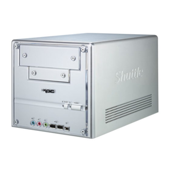
< 1.3 XPC Exterior Dissection Note : Shuttle offers a variety of different XPC models loaded with various options. The illustration below will help familarize you with the included features in your new XPC. < 1.3.1 XPC Front 1. 5.25" Bay 2. -
Page 12: Xpc Back
< 1.3.2 XPC Back AC Power socket COM port VGA port FireWire® 400 port 1394 USB Ports LAN port PS/2 Mouse Wireless LAN perforation Parallel port perforation PS/2 Keyboard Line-In port Central / Bass Rear out(R/L) Front out (R/L) Clear CMOS button... -
Page 13: Accessories
10. RAID manual (1) 11. Motherboard CD Driver(32bits/64bits) (2) 12. Shuttle Extras CD (1) 13. RAID Driver Floppy Disk (32bits/64bits) (2) Note : Bundled Accessories may differ from specified. If there are items missing, please contact your local authorized Shuttle dealer. -
Page 14: Xpc Mainboard
< 1.5 XPC Mainboard < 1.5.1 SK21G mainboard illustration PS/2 K/B & M/S Connector LAN & Dual USB Port LINE-IN Connector 1394 & Dual USB Port SPDIF-out Header-JP8 VGA & COM Port Rear out/Front out/Center/Bass Audio Connectors Clear CMOS Button VT1617A Chip CD_IN Connector- CN11 Mini CD-IN-CN14... -
Page 15: Jumper Settings
< 1.5.2 Jumper Settings Several hardware adjustments are made by setting jumpers on the mainboard. To successfully change jumper settings, you will need to locate pin#1. In this manual, pin#1 is represented by a white square, other pins are represented by a circles. An illustration is shown below for your reference: Jumpers with two pins are shown as for Closed [On] or... -
Page 16: Front Panel Connector (Jp3/Jp9)
Front Panel Connector (JP3/JP9) Header JP3can be used to provide operation status signals to the front daughterboard. Note that this is an alternative header to the 50pins streamline header that also con- nects the motherboard to the front daughterboard. Headers JP9 is used to connect cable to front panel connector mounted on front-panel or back-panel. -
Page 17: Spdif-Out Connector(Jp8)
SPDIF-out Connector (JP8) Port JP8 provides the mainboard connection for the SPDIF-out signal port. Pin Assignments (JP8): 1=SPDIF-out signal JP 8 2=VCC 3=GND LINE-IN (CN12)(Blue), CD-IN (CN11)(Black), mini CD-IN (CN14) (White) Connectors Port CN12(Blue), CN11(Black) and CN14(White) are used to connect stereo audio inputs from a CD-ROM. -
Page 18: Clear Cmos (Jp1)
A DB25 male parallel port header is located near the rear panel of the mainboard. The header is used to connect a parallel port socket (PC8) to the mainboard. The parallel printer port can be purchased from Shuttle as an optional accessory. Pin Assignments (JP7):... -
Page 19: Xpc Installation Guide
2 XPC Installation Guide < 2.1 Installation Note : For safety reasons, please ensure that the power cord is disconnected before opening the case. < 2.1.1 Remove the Cover 1. Unscrew the four thumbscrews. 2. Slide the cover backwards and upwards. -
Page 20: Remove The Rack
< 2.1.2 Remove the Rack 1. Unbuckle the two Serial ATA HDD mounting brackets from the rack. 2. Remove the rack. 3. Unscrew and remove the front bay covers. -
Page 21: Cpu, Ddr And Ice Installation
< 2.2 CPU, DDR and ICE Installation < 2.2.1 Remove the ICE Module. 1. Unfasten the ICE fan thumbs screws on the back of the chassis. 2. Unplug the fan power connector. - Page 22 3. Unfasten the four ICE module attachment screws. 4. Remove the ICE module from the chassis and put it aside. ICE Heat-Pipe Module Smart Fan Heat-pipe Smart Fan Power Connector...
-
Page 23: Install The Cpu
< 2.2.2 Install the CPU 1. Pull up the CPU socket lever to 90-degrees. Push the lever CPU socket lever at 90 degrees 2. Match the yellow triangle on a corner of the CPU with the triangle on the socket corner and gently insert the CPU into the socket. - Page 24 3. Press down the CPU socket lever. Note : Failure to correctly align the CPU and socket can result in damage to the CPU. 4. Spread an even layer of thermal compound on the CPU die. Thermal compound application area...
-
Page 25: Install The Ice Module
< 2 .2 . 3 Install the ICE Module 1. Place the ICE module on the CPU and match the screws with the holes on the motherboard. 2. Screw the ICE module to the motherboard. Press down firmly on the opposite corner as you screw. - Page 26 4. Fasten the smart fan to the chassis with the four thumbscrews.
-
Page 27: Ddr Installation
<2.3 DDR Installation Install the DDR module in DIMM1/DIMM2. 1. Unlock the DIMM latch. 2. Align the DDR module's cutout with the DIMM slot notch. Cutout Notch Latch Latch 3. Check that the latches are closed, and the DDR module is firmly installed. -
Page 28: Cable And Rack Installation
<2.4 Cable and Rack Installation <2.4.1 Install the FDD Cable 1. Plug the FDD cable in the FDD header (FDD1). Pin 1(white line) Pin 1 (white line) Pin1 2. Fold the FDD cable under the power supply. 3. Fix the FDD cable to the power and chassis rail with the suppied adhesive tape. -
Page 29: Install The Serial Cable
< 2.4.2 Install the Serial ATA HDD Cable 1. Plug the Serial ATA cable to the SATA1 header. SATA header Purse lock 2. Loosen the purse lock and separate the Serial ATA HDD and FDD power connectors. Serial ATA Power connector... -
Page 30: Installation Rack
< 2.4.3 Install the Rack 1. Place the HDD in the rack and secure with screws from the side. 2. Place the FDD in the rack and tighten with its own screws. Note : The second screw is located at the opposite side of rack. - Page 31 3. Place the rack in the chassis. 4. Refasten the rack.
-
Page 32: Peripheral Installation
<2.5 Peripheral Installation < 2.5.1 Install the Serial ATA HDD 1. Connect the Serial ATA cable and power connector he HDD. Serial ATA Power connector Serial ATA HDD cable < 2.5.2 Install Floppy Drive 1. Connect the FDD cable and power connector into the Floppy drive. FDD connector Power connector... -
Page 33: Installation An Optical Driver
< 2.5.3 Install an Optical Drive 1. Slide optical driver into the chassis. 2.Check the optical drive front alignment and fasten the four side screws. Screws (Optical Drive) 3.Plug the optical driver and power cable into the optical drive. Optical drive Power cable Optical drive cable... -
Page 34: Accessories Installation
<2.6 Accessories Installation < 2.6.1 Install PCI/AGP Card 1. An AGP card will be used to demonstrate the installation procedure. AGP Card 2.Unfasten expansion slot bracket screws and remove the aluminum back panel breket. Put the back panel bracket aside. Lift Up AGP Door Bracket... -
Page 35: Final Touches
< 2.7 Final Touches < 2.7.1 Close the Chassis Cover 1. Replace the cover and refasten the thumbscrews. -
Page 36: Complete
< 2 .7 . 2 Com pl et e < 2 . 8 XPC Accessories Shuttle offers over 25 great upgrade and modding kits for your XPC. Visit our website at http://www.shuttle.com for more information or speak to your local retailer. -
Page 37: A Technical Notes
< 2.A Technical Notes < 2.A.1 Clear CMOS Button This XPC comes enhanced with an easy-to-use Clear CMOS Button. This button allows users to reset BIOS information to factory default settings. 1. Power down the XPC and remove the power cord. 2. -
Page 38: Driver And Software Installation
Install Utility - Install Acrobat Reader, WinFlash Utility. Manual - SK21G user's guide and RAID manual in PDF format. Link to Shuttle Homepage - Link to shuttle website homepage. Browse this CD - Allows you to see contents of this CD. -
Page 39: Install Mainboard Software
Insert the attached CD into your CD-ROM drive. The CD AutoRun screen should appear. If the AutoRun screen does not appear, double click on Autorun icon in My Computer to bring up Shuttle Mainb-oard Software Setup screen. Click the “Install Main-board Software“ bar. Individually install the following drivers. -
Page 40: Appendix
Appendix BIOS Settings The SK21G BIOS ROM has a built-in Setup program that allows users to modify basic system configuration. This information is stored in battery-backed RAM so that it re- tains Setup information even if the system power is turned off. The system BIOS manages and executes a variety of hardware related functions including: System date and time... -
Page 41: The Main Menu
The Main Menu Once you enter the AwardBIOS(tm) CMOS Setup Utility, the Main Menu will appear on the screen. The Main Menu allows you to select from sev- eral setup functions and two exit choices. Use the arrow keys to select among the items and press <Enter>... - Page 42 PC Health Status This entry displays the current system temperature, Voltage, and FAN settings. Frequency Control Use this menu to specify your settings for ratio control. Load Fail-Safe Defaults Use this menu to load the BIOS default values for the minimal/stable per- formance of your system to operate.
-
Page 43: Standard Cmos Features
Standard CMOS Features The items in the Standard CMOS Setup Menu are divided into several categories. Each category includes none, one or more than one setup items. Use the arrow keys to highlight the item and then use the <PgUp> or <PgDn>... - Page 44 Halt On Select the situation in which you want the BIOS to stop the POST process and notify you. Ø The choice: All Errors, No Errors, All, But Keyboard, All, But Diskette, or All, But Disk/Key. Base/Extended/Total Memory Theseitems are automatically detected by the system at start up time. These are display-only fields.
- Page 45 Cylinder Set the number of cylinders for this hard disk. Ø Min = 0, Max = 65535 Head Set the number of read/write heads. Ø Min = 0, Max = 255 Precomp Warning: Setting a value of 65535 means no hard disk. Ø...
-
Page 46: Advanced Bios Features
Advanced BIOS Features This section allows you to configure your system for basic operation. You have the opportunity to select the system's default speed, boot-up sequence, keyboard operation, shadowing, and security. Hard Disk Boot Priority This item allows you to select Hard Disk Book Device Priority. BIOS Write Protect The item allows you to enable/disable the Bios Write Protect. - Page 47 CPU Internal Cache All processors that can be installed in this mainboard use internal level 1 (L1) cache memory to improve performance. Leave this item at the de- fault value for better performance. Ø The choice: Enabled or Disabled. External Cache Most processors that can be installed in this system use external level 2 (L2) cache memory to improve performance.
- Page 48 Boot Up Floppy Seek Seeks disk drives during boot-Up. Disabling speed boots up. Enabled tests floppy drives to determine whether they have 40 or 80 tracks. Ø The choice: Enabled or Disabled. Boot Up NumLock Status Selects power on state for NumLock. Ø...
- Page 49 HDD Security Freeze Lock Selects enable/disable HDD Security Freeze Lock, Enabled - prevents any external application from locking Hard drive except for BIOS. Ø The choice: Enabled or Disabled. APIC Mode Selects enable/disable IO APIC function Ø The choice: Enabled or Disabled. MPS Version Control For OS Selects the operating system multiprocessor support version.
-
Page 50: Advanced Chipset Features
Advanced Chipset Features This section allows you to configure the system based on the specific features of the installed chipset. This chipset manages bus speeds and access to system memory resources, such as DRAM and the external cache. It also coordinates communications between the conventional ISA bus and the PCI bus. - Page 51 AGP Driving Control This item enables the system to automatically select its output buffer drive strength or make it manually selectable by an end user. Ø The Choice: Auto or Manual. AGP Driving Value This item enables an end user to manually select the AGP output buffer drive strength.
- Page 52 DDR Timing Setting This item allows you to set DRAM timing. Ø The Choice: Auto or Manual. Memclock index valux (Whz) Places an artificial memory clock limit on the system. Memory is prevented from running faster than this frequency. Ø The Choice: 100, 133,166 or 200. CAS# latency (Tc1) This item defines the timing delay in clock cycles before SDRAM starts a read command after receiving it.
- Page 53 LDT & PCI Bus Control Options are in its sub-menu. Press <Enter> to enter the sub-menu of detailed options. Upstream LDT Bus Width This item allows you to select the LDT upstream width. Ø The Choice: 8 bit or 16 bit. Downstream LDT Bus Width This item allows you to select the LDT downstream width.
- Page 54 PCI Delay Transaction The chipset has an embedded 32-bit posted write buffer to support delay transactions cycles. Select Enabled to support compliance with PCI specification version 2.1. Ø The Choice: Enabled or Disabled. Memory Hole You can reserve this area of system memory for ISA adapter ROM. When this area is reserved, it can't be cached.
-
Page 55: Integrated Peripherals
Integrated Peripherals VIA OnChip IDE Device Option are in its sub-menu. Press<Enter>to enter the sub-menu of detailed options. OnChip SATA The chipset contains a SATA interface with support to on SATA channel. Select Enabled to active the primary SATA interface. Select Disabled to deactivate the primary interface. - Page 56 SATA Mode You can select SATA Mode as "RAID" to run RAID bios and make raid. Ø The choice: IDE or RAID. OnChip IDE Channel0 The chipset contains a PCI IDE interface with support to two IDE channels. Select Enabled to activate the primary IDE interface; select Dis- abled to deactivate this interface.
- Page 57 Onboard Audio This item allows you to select audio chip to support Audio. Disable this item. If you are going to install a PCI audio add-on card. Ø The Choice: Auto or Disabled. Onboard LAN This item allows you to select onchip LAN. Ø...
- Page 58 Parallel Port Mode Select an operating mode for the onboard parallel (printer) port. Select Normal, Compatible, or SPP unless you are certain your hardware and software both support one of the other available modes. Ø The choice: SPP, EPP, ECP or ECP+EPP. ECP Mode Use DMA When the onboard parallel is set to ECP mode, the parallel port can use DMA3 or DMA1.
-
Page 59: Power Management Setup
Power Management Setup The Power Management Setup allows you to configure your system to most effectively saving energy while operating in a manner consistent with your own style of computer use. ACPI Function This item allows you to enable/disable the Advanced Configuration and Power Management (ACPI). - Page 60 saving mode. Ø The choice: Suspend->off or Always On. Video Off Method This determines the manner in which the monitor is blanked. Blank Screen This option only writes blanks to the video buffer. V/H SYNC+Blank This selection will cause the system to turn off the vertical and horizontal synchronization ports and write blanks to the video buffer.
- Page 61 PS2KB Wakeup from S3/S4/S5 Set a key to awaken the system from a keyboard. Ø The choice: Disable, Ctrl+F1~Ctrl+F12, Power, Wake or Any Key. PS2MS Wakeup from S3/S4/S5 This item enables or disables the PS/2 mouse to awaken the system. Ø...
- Page 62 Data (of Month) This item selects the alarm date. Ø Key in a DEC number: Min=0, Max=31. Resume Time (hh:mm:ss) This item selects the alarm Time. [hh] Ø Key in a DEC number: Min=0, Max=23. [mm] Ø Key in a DEC number: Min=0, Max=59. [ss] Ø...
-
Page 63: Pnp/Pci Configurations
PnP/PCI Configurations This section configures how PnP and PCI operate in your system. Correctly setting up the IRQ and DMA (both PnP and PCI use) assign- ments will make your system work stably. It is strongly recommended that only technical users make changes to the default settings. PNP OS Installed This item allows you to determine PnP OS is installed or not. - Page 64 IRQ Resources When resources are controlled manually, assign each system interrupt a type, depending on the type of device using the interrupt. IRQ3/4/5/7/9/10/11/12/14/15 assigned This item allows you to determine the IRQ assigned to the ISA bus and is not available to any PCI slot. Legacy ISA for devices is compliant with the original PC AT bus specification;...
-
Page 65: Pc Health Status
PC Health Status CPU Fan Speed Control Here you can set the ICE Fan Speed. Ø The choice: Smart Fan, Ultra-Low, Low , Mid , or Full . Note : Before manually modifying the CPU fan setting, please make sure fan connectors are plug ged into the correct fan connector on the mainboard. -
Page 66: Frequency Control
Frequency Control Auto Detect PCI Clk This item allows you to enable/disable auto detection PCI Clock. Ø The choice: Enabled or Disabled. Spread Spectrum This item allows you to enable or disable the spread spectrum modulation. Ø The choice: Disabled or Enabled. CPU Clock This item allows you to adjust CPU Host Clock. -
Page 67: Load Fail-Safe Defaults
Load Fail-Safe Defaults When you press <Enter> on this item, you will get a confirmation dialog box with a message similar to: Load Fail-Safe Defaults (Y/N) ? N Pressing 'Y' loads the BIOS default values for the most stable, minimal performance system operations. -
Page 68: Save & Exit Setup
New Password Setting: 1. While pressing <Enter> to set a password, a dialog box appears to ask you enter a password. 2. Key in a new password. The password can not exceed eight characters. 3. System will request you to confirm the new password again. 4. - Page 69 SK21G...
- Page 70 SK 21G...
- Page 71 SK 21G...
- Page 72 SK 21G...
Need help?
Do you have a question about the XPC SK21G and is the answer not in the manual?
Questions and answers