Table of Contents
Advertisement
Quick Links
Advertisement
Table of Contents

Related Manuals for Shuttle XPC SN26P


Summary of Contents for Shuttle XPC SN26P
- Page 1 XPC User Guide For the : SN26P...
- Page 2 Statement of Shuttle Mainboard via the EMI Test Shuttle mainboards have been via the EMI test in terms of series of regulations: EN55022/ CISPR22/AS/NZS3548 Class B, EN55024 (1998/AS/NZS), EN4252.1 (1994), EN61000, ANSI C63.4 (1992), CFR47 Part 15 Subpart B, and CNS13438 (1997). The items tested are illus- trated as follows: (A) Voltage: AC 110V/60HZ &...
- Page 3 (C) Remedy for the Tested Product & Its EMI Interference: Remedy: N/A EMI Interference: Crystal : 32.768 KHz(X8)/ 25 MHz(X7)/ 22.5 MHz(X9)/ 24.576 MHz(X10)/ 24.576 MHz(X6) (D) Supported Host Peripherals: Host Peripheral Product Name Model Name Case SN26P Power Supply PC43I3503 Serial ATA II HITACHI S2VT9K9M...
- Page 4 2. This device must accept any interference received, including interference that may cause undesired operation. Trademarks Shuttle is a registered trademark of Shuttle Inc. Intel and Pentium are registered trademarks of Intel Corporation. PS/2 is a registered trademark of IBM Corporation.
- Page 5 Read the following precautions before setting up a Shuttle XPC. CAUTION Incorrectly replacing the battery may damage this computer. Replace only with the same or equivalent as recommended by Shuttle. Dispose of used batteries according to the manufacturer's instructions. Installation Notices Do not place this device underneath heavy loads or in an unstable position.
-
Page 6: Table Of Contents
TABLE OF CONTENTS 1 Function Introduction ..................1 1.1 XPC Introduction ................... 1 1.2 Model Specifications ..................2 1.3 XPC Exterior Dissection ................3 1.3.1 XPC Front ..................... 3 1.3.2 XPC Back ..................... 4 1.4 Accessories ....................5 1.5 XPC Mainboard ....................6 1.5.1 SN26P mainboard illustration .............. - Page 7 2.3 Peripheral Installation ................20 2.3.1 Install the serial ATA HDD ..............20 2.3.2 Optical Drive Rack Mounting ..............20 2.3.3 Install the Rack Peripherals ..............21 2.3.4 Install more Serial ATA HDDs ............... 24 2.4 Accessories Installation ................26 2.4.1 Install PCI Express x16 Card ..............
- Page 8 PnP/PCI Configurations ................53 PC Health Status ..................55 Ratio/Voltage Control ................... 57 Load Fail-Safe Defaults ................58 Load Optimized Defaults ................58 Set Supervisor/User Password ..............58 Save & Exit Setup ..................59 Exit Without Saving ..................59...
-
Page 9: Function Introduction
The XPC has been designed to be easily assembled and configured directly by the end user. Consumers can choose to buy preconfigured, ready-to-run XPC’ s as well~a list of Shuttle-authorized value-added resellers can be found at www. shuttle.com. -
Page 10: Model Specifications
< 1.2 Model Specifications Form Factor Shuttle Small Form Factor Processor AMD 939 pin package with 200MHz x 5 FSB Chipset nVIDIA nForce 4 SLI Memory 184 pins 333/400 DDR SDRAM DIMM X2 with Dual-Channel Mode configuration Supports 256Mb,512Mb, and 1Gb technologies for X8 and X16 devices Audio H/W Audio Envy24 (7.1-CHANNEL) -
Page 11: Xpc Exterior Dissection
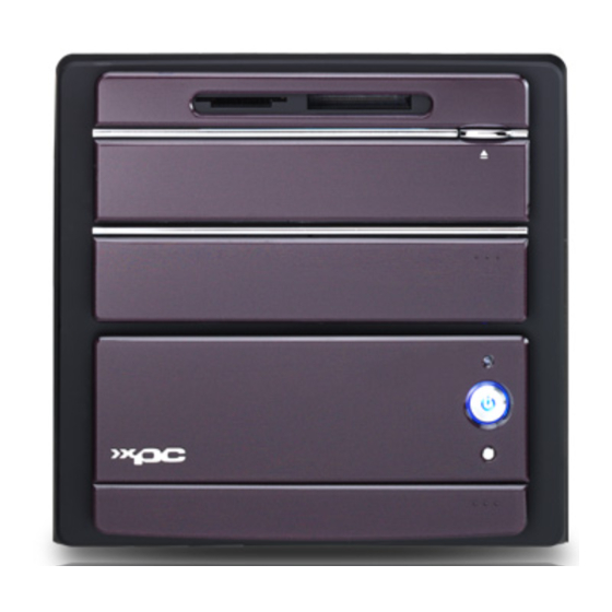
< 1.3 XPC Exterior Dissection Note : Shuttle offers a variety of different XPC models loaded with various options. The illustration below will help familarize you with the included features in your new XPC. < 1.3.1 XPC Front 1. Card R/W (MS, MS Pro, MMC, SD, SM) 2. -
Page 12: Xpc Back
< 1.3.2 XPC Back AC power switch AC power socket COM port Clear CMOS Clear CMOS button PS/2 Mouse PS/2 Keyboard LAN port USB ports FireWire® 400 port SPDIF OUT (Coaxial) 1394 SPDIF OUT (Optical) Central/Bass Side Surr (R/L) SPDIF IN (Optical) Front OUT (R/L) Surround back (R/L) Line IN port... -
Page 13: Accessories
11. SLI bridge card (1) 12. Heatsink compound (1) 13. RAID Driver Floppy Disk (1) 14. XPC user guide (1) 15. RAID manual (1) Note : Bundled Accessories may differ from specified. If there are items missing, please contact your local authorized Shuttle dealer. -
Page 14: Xpc Mainboard
< 1.5 XPC Mainboard < 1.5.1 SN26P mainboard illustration Giga LAN (GbE) & USB 2.0 Port PS/2 Keyboard/Mouse Port 1394 & USB 2.0 Port Wireless KB/MS Header- JP2 SPDIF-OUT Coaxial/Optical Ports COM Port & Clear CMOS Button SPDIF-IN Optical/ Surround-Out/ Center/Bass/ Front-Out/ FAN Connector- FAN4... -
Page 15: Jumper Settings
< 1.5.2 Jumper Settings Several hardware adjustments are made by setting jumpers on the mainboard. To successfully change jumper settings, you will need to locate pin#1. In this manual, pin#1 is represented by a white square, other pins are represented by a circles. An illustration is shown below for your reference: Jumpers with two pins are shown as for Closed [On] or... -
Page 16: Front Panel Audio/Usb/1394 Connector (Jp6/Jp16)
Front Panel AUDIO/ USB/ 1394 Connector (JP6/JP16) Headers JP6 and JP16 are used to connect cables to front panel connectors mounted on front-panel or back-panel. The front panel is where the hard drive activity lights, reset button, on/off button, computer power on light, USB connectors, 1394 connectors, and audio headers, are located. -
Page 17: Fan Connectors (Fan1/Fan2/Fan3/Fan4)
Fan Connectors (FAN1/FAN2/FAN3/FAN4) The mainboard provides four onboard 12V cooling fan power connectors to support CPU_In (FAN1), CPU_Out (FAN2), chipset (FAN3), Reserved (FAN4) fans. PWM_CTRL SPEED_SENSE SPEED_SENSE +12V +12V GNDt Note : Both cable wiring and type of plug may vary depending on the fan maker. -
Page 18: Wireless Keyboard And Mouse Connectors (Jp2)
Wireless Keyboard and Mouse Connectors (JP2) JP2 header provides support for a wireless keyboard and mouse. The four mini Jump- ers must be set on the 5-6, 7-8, 9-10 pins and 11-12 pins when this header is not in use. Pin Assignments (JP2): 1=VCC 2=VCC... -
Page 19: Usb Header (Usb3)
A DB25 male parallel port header is located near the rear panel of the mainboard. The header is used to connect a parallel port socket (PC15) to the mainboard. The parallel printer port can be purchased from Shuttle as an optional accessory. Pin Assignments (J1):... -
Page 20: Xpc Installation Guide
2 XPC Installation Guide < 2.1 Installation Note : For safety reasons, please ensure that the power cord is disconnected before opening the case. < 2.1.1 Remove the Cover 1. Unscrew the four thumbscrews. 2. Slide the cover backwards and upwards. -
Page 21: Remove The Rack
< 2.1.2 Remove the Rack 1. Unbuckle the two Serial ATA HDD mounting brackets from the rack. Serial ATA HDD mounting brackets 2. Remove the rack. -
Page 22: Cpu, Ddr And Ice Installation
< 2.2 CPU, DDR and ICE Installation < 2.2.1 Remove the ICE Module 1. Unplug the fan power connector. 2. Unfasten the four ICE module attachment screws. 3. Remove the ICE module from the chassis and put it aside. -
Page 23: Install The Cpu
ICE Heat-Pipe Module Heat-pipe Smart Fan Power Connector Smart Fan < 2.2.2 Install the CPU 1. Pull up the CPU socket lever to 90-degrees. CPU socket lever at 90 degrees Push the lever 2. Match the yellow triangle on a corner of the CPU with the triangle on the socket corner and gently insert the CPU into the socket. - Page 24 Triangle Markings 3. Press down the CPU socket lever. Note : Failure to correctly align the CPU and socket can result in damage to the CPU. 4. Spread an even layer of thermal compound on the CPU die.
-
Page 25: Ddr Installation
< 2.2.3 DDR Installation Memory Configuration : Install memory in any or all of the banks according to the combinations shown below. TOTAL 2 DIMM in Single or Dual Channel Mode up to 2GB and 1GB per DIMM Density 256 Mbit 512 Mbit 1024 Mbit Device Width... - Page 26 2. Align the DDR module's cutout with the DIMM slot notch. Insert the DDR module into the DIMM1 slot (blue) first. If you have only one DIMM, it must be installed in the blue slot. Cutout Notch Latch Latch 3. Check that the latches are closed, and the DDR module is firmly installed. Note : Repeat to install a second DDR module if desired.
-
Page 27: Install The Ice Module
< 2.2.4 Install the ICE Module 1. Place the ICE module on top of the CPU die and match the screws with the holes on the motherboard. 2. Screw the ICE module to the motherboard. Note to press down on the opposite diagonal corner while tightening each screw. -
Page 28: Peripheral Installation
< 2.3 Peripheral Installation Note : The rack is designed for one 3.5" serial ATA hard drive only. < 2.3.1 Instal the serial ATA HDD 1. Place the HDD in the rack and secure with screws from the side. Note : Secure with two screws on each side. -
Page 29: Install The Rack Peripherals
3. Slide the optical drive into the rack until the ends of the brackets are secured in the rack as shown. < 2.3.3 Install the Rack Peripherals 1. Looking at the inside of the stealth drive door, check the alignment of the drive's eject button with this XPC's drive eject mechanism. - Page 30 3. Place the rack in the chassis. Note : Move the card reader's signal cable so as to not crimp it during this process. 4. Connect the card reader's signal cable. 5. Connect the Serial ATA and power cables to the HDD. Serial ATA Cable Serial ATA Power Cable...
- Page 31 6. Plug the optical drive cable and power cable into the optical drive. Optical Drive Cable Optical Drive Power Cable Note : If you are not installing more Serial ATA HDDs, proceed to step 7. If you are installing more Serial ATA HDDs, proceed to 2.3.4. 7.
-
Page 32: Install More Serial Ata Hdds
< 2.3.4 Install more Serial ATA HDDs 1. Take two HDD mounting brackets. Serial ATA HDD mounting brackets 2. Align the pins on the mounting brackets with the holes on the HDD and attach. Note : The mounting brackets are side specific. 3. - Page 33 4. Buckle the HDD into position. 5. Connect the Serial ATA signal and power cable to the HDD. Serial ATA Power cable Serial ATA HDD cable...
-
Page 34: Accessories Installation
< 2.4 Accessories Installation < 2.4.1 Install PCI Express x16 Card 1. A PCI Express x16 card will be used to demonstrate this installation procedure. Unfasten the expansion slot bracket screws and remove the back panel bracket. Put the brackets aside. Lift up Slot Bracket PCI Express x16 slot... - Page 35 3. Connect the VGA power cable as shown below. 4. Repeat to install a second PCI Express x16 card as shown below. 5. Secure the bracket.
-
Page 36: Install Sli Bridge Card
Note : Refer to section 2.4.2 if you are installing two PCI Express x16 Cards. < 2.4.2 Install SLI bridge card 1. Take out the SLI bridge card from the accessory box. 2. Install the SLI bridge card as shown below. Note : SLI technology (Scalable Link Interface) could support 2 PCI Express x16 cards and be operated parallel at the same... -
Page 37: Final Touches
< 2.5 Final Touches < 2.5.1 Close the Chassis Cover 1. Replace the cover and refasten the thumbscrews. < 2.5.2 Install Front Feet 1. Take out the two front feet from the accessory box. Front feet 2. Screw the front feet to the base of the chassis. -
Page 38: Complete
< 2.5.3 Complete < 2.6 XPC Accessories Shuttle offers over 25 great upgrade and modding kits for your XPC. Visit our website at http://www.shuttle.com for more information or speak to your local retailer. < 2.7 Tech Support Shuttle Inc. http://www.shuttle.com Tech Support http://global.shuttle.com/Support/Support.asp... -
Page 39: Technical Notes
< 2.8 Technical Notes < 2.8.1 Clear CMOS Button This XPC comes enhanced with an easy-to-use Clear CMOS Button. This button allows users to reset BIOS information to factory default settings. 1. Power down the XPC and remove the power cord. 2. -
Page 40: Driver And Software Installation
Install Utility - Install Acrobat Reader, WinFlash Utility. Manual - SN26P user's guide and nVIDIA manual in PDF format. Link to Shuttle Homepage - Link to shuttle website homepage. Browse this CD - Allows you to see contents of this CD. -
Page 41: Install Mainboard Software
Insert the attached CD into your CD-ROM drive. The CD AutoRun screen should appear. If the AutoRun screen does not appear, double click on Autorun icon in My Computer to bring up Shuttle Mainb-oard Software Setup screen. Click the “Install Main-board Software“ bar. Individually install the following drivers. -
Page 42: Appendix
Appendix BIOS Settings The SN26P BIOS ROM has a built-in Setup program that allows users to modify basic system configuration. This information is stored in battery-backed RAM so that it re- tains Setup information even if the system power is turned off. The system BIOS manages and executes a variety of hardware related functions including: System date and time... -
Page 43: The Main Menu
The Main Menu Once you enter the AwardBIOS(tm) CMOS Setup Utility, the Main Menu will appear on the screen. The Main Menu allows you to select from sev- eral setup functions and two exit choices. Use the arrow keys to select among the items and press <Enter>... - Page 44 PC Health Status This entry displays the current system temperature, Voltage, and FAN settings. Ratio/Voltage Control Use this menu to specify your settings for ratio control. Load Fail-Safe Defaults Use this menu to load the BIOS default values for the minimal/stable per- formance of your system to operate.
-
Page 45: Standard Cmos Features
Standard CMOS Features The items in the Standard CMOS Setup Menu are divided into several categories. Each category includes none, one or more than one setup items. Use the arrow keys to highlight the item and then use the <PgUp> or <PgDn>... - Page 46 Halt On Select the situation in which you want the BIOS to stop the POST process and notify you. Ø The choice: All Errors, No Errors, All, But Keyboard, All, But Diskette, or All, But Disk/Key. Base/Extended/Total Memory Theseitems are automatically detected by the system at start up time. These are display-only fields.
- Page 47 Cylinder Set the number of cylinders for this hard disk. Ø Min = 0, Max = 65535 Head Set the number of read/write heads. Ø Min = 0, Max = 255 Precomp Warning: Setting a value of 65535 means no hard disk. Ø...
-
Page 48: Advanced Bios Features
Advanced BIOS Features This section allows you to configure your system for basic operation. You have the opportunity to select the system's default speed, boot-up sequence, keyboard operation, shadowing, and security. Hard Disk Boot Priority This item allows you to select Hard Disk Book Device Priority. BIOS Write Protect The item allows you to enable/disable the Bios Write Protect. - Page 49 CPU Internal Cache All processors that can be installed in this mainboard use internal level 1 (L1) cache memory to improve performance. Leave this item at the de- fault value for better performance. Ø The choice: Enabled or Disabled. External Cache Most processors that can be installed in this system use external level 2 (L2) cache memory to improve performance.
- Page 50 Gate A20 Option This entry allows you to select how the gate A20 is handled. The gate A20 is a device used for above 1MByte of address memory. Initially, the gate A20 was handled via a pin on the keyboard. Today, while a key- board still provides this support, it is more common and much faster in setting to Fast for the system chipset to provide support for gate A20.
- Page 51 HDD Security Freeze Lock Selects enable/disable HDD Security Freeze Lock, Enabled - prevents any external application from locking Hard drive except for BIOS. Ø The choice: Enabled or Disabled. APIC Mode Selects enable/disable IO APIC function Ø The choice: Enabled or Disabled. MPS Version Control For OS Selects the operating system multiprocessor support version.
-
Page 52: Advanced Chipset Features
Advanced Chipset Features This section allows you to configure the system based on the specific features of the installed chipset. This chipset manages bus speeds and access to sys- tem memory resources, such as DRAM and the external cache. It also coordi- nates communications between the conventional ISA bus and the PCI bus. - Page 53 Memclock index value (Mhz) Places an artificial memory clock limit on the system. Memory is prevented from running faster than this frequency. Ø The Choice: 100Mhz, 133Mhz, 166Mhz, 200Mhz, 216Mhz, 233Mhz or 250Mhz. CAS# latency (Tcl) When synchronous DRAM is installed, the number of clock cycles of CAS latency depends on the DRAM timing.
- Page 54 SATA Spreed Specturm This item allows you to set the SATA Spreed Specturm. Ø The choice: Down Spreed or Disabled. PCIE Spreed Specturm This item allows you to set the SATA Spreed Specturm. Ø The choice: Down Spreed or Disabled. SSE/SSE2 Instructions This item allows you to enable/disable the SSE/SSE2 Instructions.
-
Page 55: Integrated Peripherals
Integrated Peripherals Onboard IDE Device Options are in its sub-menu. Press <Enter> to enter the sub-menu of detailed options. RAID Function Setup Press <Enter> to enter the RAID Function. OnChip IDE Channel 0 The chipset contains a PCI IDE interface with support to two IDE channels. Select Enabled to activate the primary IDE interface. - Page 56 Serial-ATA 1/2 This item allows you to enable/disable the Serial-ATA 1/2. Ø The choice: Enabled or Disabled. SATA DMA transfer This item allows you to enable/disable the SATA transfer access. Ø The choice: Enabled or Disabled. IDE Prefetch Mode The onboard IDE drive interface support IDE prefetching for faster drive access.
- Page 57 Onboard FDC Controller This item specifices onboard floopy disk drive controller. This setting allows you to connect your floopy disk drives to the onboard floopy connector. Ø The Choice: Enable or Disabled. Onboard Serial Port1 This option is used to assign the I/O address and interrupt request(IRQ) for the onboard serial port1(COM1).
-
Page 58: Power Management Setup
Power Management Setup The Power Management Setup allows you to configure your system to most effectively saving energy while operating in a manner consistent with your own style of computer use. ACPI Function This item allows you to enable/disable the Advanced Configuration and Power Management (ACPI). - Page 59 Video Off Method This determines the manner in which the monitor is blanked. V/H SYNC+Blank This selection will cause the system to turn off the vertical and horizontal synchronization ports and write blanks to the video buffer. Blank Screen This option only writes blanks to the video buffer. DPMS Supported Initial display power management signaling.
- Page 60 USB Resume From S3 If you are using a USB keyboard, and the ACPI suspend type is set to S3, you can enable this item to allow a keystroke to wake up the system from power saving mod. Ø The choice: Enabled or Disabled. Power-On by Alarm When set to Enabled, the following three fields become available and you can set the month, date (day of the month), hour, minute and second...
-
Page 61: Pnp/Pci Configurations
PnP/PCI Configurations This section describes the configuration of PCI bus system. PCI or Per- sonal Computer Interconnection is a system which allows I/O devices to operate at the speed CPU itself keeps when CPU communicating with its own special components. This section covers some very technical items, and it is strongly recom- mended that only experienced users should make any changes to the default settings. - Page 62 IRQ Resources When resources are controlled manually, assign each system interrupt a type, depending on the type of device using the interrupt. IRQ3/4/5/7/9/10/11/12/14/15 assigned This item allows you to determine the IRQ assigned to the ISA bus and is not available to any PCI slot. Legacy ISA for devices is compliant with the original PC AT bus specification;...
-
Page 63: Pc Health Status
PC Health Status Advanced CPU Fan Setting Set the CPU Fan Speed. ØThe choice : Smart Fan, Noise Control - U Low, Noise Control - Low, Noise Control - Mid, Noise Control - Full, Temp Control - 50 C, Temp Control - 55 Temp Control - 60 C or Temp Control - 65 Smart Fan : The CPU fan speed will be increased when the temperature... - Page 64 Temp Control-55 C : When the CPU fan being set up as auto-modified, the temperature of CPU will be remained as 55 Temp Control-60 C : When the CPU fan being set up as auto-modified, the temperature of CPU will be remained as 60 Temp Control-65 C : When the CPU fan being set up as auto-modified, the temperature of CPU will be remained as 65...
-
Page 65: Ratio/Voltage Control
Ratio/Voltage Control CPU Ratio This item allows you to set the CPU Ratio. Ø The choice: x4 800Mhz, x5 1000Mhz, x6 1200Mhz, x7 1400Mhz, x8 1600Mhz, x9 1800Mhz, x10 2000Mhz, x11 2200Mhz, x12 2400Mhz, x13 2600Mhz, x14 2800Mhz, x15 3000Mhz, x16 3200Mhz, x17 3400Mhz, x18 3600Mhz, x19 3800Mhz, x20 4000Mhz, x21 4200Mhz, x22 4400Mhz, x23 4600Mhz, x24 4800Mhz, x25 5000Mhz or Auto. -
Page 66: Load Fail-Safe Defaults
Load Fail-Safe Defaults When you press <Enter> on this item, you will get a confirmation dialog box with a message similar to: Load Fail-Safe Defaults (Y/N) ? N Pressing 'Y' loads the BIOS default values for the most stable, minimal performance system operations. -
Page 67: Save & Exit Setup
New Password Setting: 1. Press the <Enter> key. A dialog box appears to ask you to “Enter password: “. 2. Key in a new password. The password can not be over eight characters or numbers. 3. The system will then request you to confirm the new password by asking you to key in the new password again. - Page 68 SN26P...
Need help?
Do you have a question about the XPC SN26P and is the answer not in the manual?
Questions and answers