Advertisement
NS3552-16P-2T-2S Quick Installation Guide
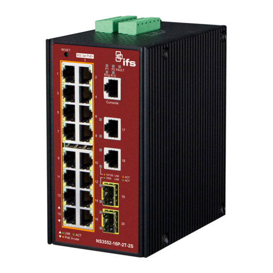
Figure 1: NS3552-16P-2T-2S Industrial L2+ Multi-port Full Gigabit
Managed Ethernet Switch
Package contents
Thank you for purchasing the NS3552-16P-2T-2S IFS L2+
industrial managed switch. The descriptions of this model are
as follows:
Industrial 16-Port 10/100/1000T 802.3at PoE +
2-Port 10/100/100T
+ 2-Port 100/1000X SFP Managed Switch
Unless specified, the term "industrial managed switch"
mentioned in this quick installation guide refers to the NS3552-
16P-2T-2S.
Open the box of the industrial managed switch and carefully
unpack it. The box should contain the following items:
The industrial managed switch × 1
Quick installation guide × 1
CD with user manual × 1
DIN rail kit × 1
Wall mounting kit × 1
DB9 to RJ45 interface RS232 console cable × 1
Dust cap (see the table below)
RJ45 Dust Cap
NS3552-16P-2T-2S
If any of these are missing or damaged, contact your dealer
immediately. If possible, retain the carton including the original
packing materials for repacking the product in case there is a
need to return it to us for repair.
© 2019 United Technologies Corporation.
Interlogix is part of UTC Climate, Controls & Security, a unit of United Technologies Corporation. All rights reserved. All trademarks are the
property of their respective owners. Information in this document is subject to change without notice.
SFP Dust Cap
19
2
Requirements
The industrial managed switch
interface for management purposes. The following equipment
is necessary for further management:
Workstation is installed with Ethernet NIC (Network
Interface Card)
Choice of Internet browsers includes Windows
Vista, Windows 7, Windows 8, Windows 10, MAC OS X,
Linux, Fedora, Ubuntu, or other platforms compatible with
TCP/IP protocols.
The above workstation has a web browser and JAVA
runtime environment plug-in installed.
Ethernet port connection
Use standard network (UTP) cables with RJ45
connectors.
Note: We recommend using Internet Explorer 11.0 or later to
access the industrial managed switch.
Wiring the power inputs
The upper panel of the industrial managed switch indicates a
DC inlet power socket and consists of one terminal block
connector within six contacts. Follow the steps below to insert
the power wire:
1.
Insert the positive/negative DC power wires into contacts 1
and 2 for Power 1, or 5, and 6 for Power 2.
NS3552-16P-2T-2S : DC 48~56V
Figure 2: NS3552-16P upper panel
2.
Tighten the wire-clamp screws to prevent the wires from
loosening.
P/N 1073222-EN • REV C • ISS 01FEB19
provides a
remote login
®
XP/2003,
Advertisement
Table of Contents

Related Manuals for Interlogix NS3552-16P-2T-2S


Summary of Contents for Interlogix NS3552-16P-2T-2S
- Page 1 P/N 1073222-EN • REV C • ISS 01FEB19 Interlogix is part of UTC Climate, Controls & Security, a unit of United Technologies Corporation. All rights reserved. All trademarks are the property of their respective owners. Information in this document is subject to change without notice.
- Page 2 Power 1 Power 2 Positive (+) Pin Negative (-) Pin Ensure that the DIN-rail is secured to the track. NS3552-16P Pin 1/5 Pin 2/6 Note: The wire gauge for the terminal block should be in the range from 12 to 24 AWG. Mounting Note: Ensure that the industrial managed switch is mounted...
-
Page 3: Terminal Setup
Log in to the console. After the terminal has been connected to the device, power on the industrial managed switch. The terminal displays “running testing procedures”. When the following dialog box in Figure 4 below appears, type the factory default user name "admin" and password “admin”. User name: admin Password: admin Figure 4: Console login screen... -
Page 4: Starting Web Management
Enter as shown in Figure 5. NS3552-16P-2T-2S# configure terminal For example, if the default IP address of the industrial NS3552-16P-2T-2S (config)# interface vlan 1 managed switch is 192.168.0.100, then the manager computer NS3552-16P-2T-2S (config-if-vlan)# ip address 192.168.1.100 should be set to 192.168.0.x (where x is a number between 1 255.255.255.0... -
Page 5: Resetting The Switch To Default
The switch menu on the left side of the web page permits North America access all the functions and status provided by the +1 855.286.8889 industrial managed switch. techsupport@interlogix.com www.interlogix.com/support Latin America +1 561-998-6114 latam@interlogix.com Europe, Middle East, and Africa Select Contact Us at www.firesecurityproducts.com...
Need help?
Do you have a question about the NS3552-16P-2T-2S and is the answer not in the manual?
Questions and answers