Advertisement
Quick Links
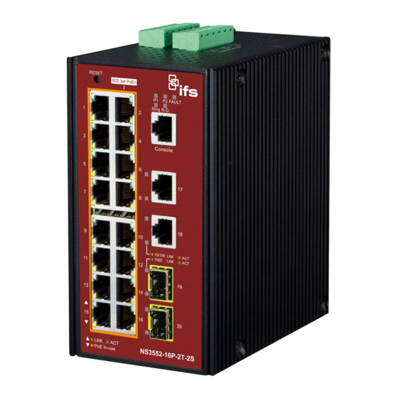
NS3552-16P-2T-2S Quick Installation Guide
Figure 1: NS3552-16P-2T-2S Industrial L2+ Multi-port Full Gigabit
Managed Ethernet Switch
1. Package Contents
Thank you for purchasing IFS L2+ Industrial Managed Switch,
NS3552-16P. The descriptions of this model are as follows:
Industrial 16-Port 10/100/1000T 802.3at PoE +
2-Port 10/100/100T
+ 2-Port 100/1000X SFP Managed Switch
"Industrial Managed Switch" mentioned in this Quick
Installation Guide refers to the above seven models.
Open the box of the Industrial Managed Switch and carefully
unpack it. The box should contain the following items:
The Industrial Managed Switch x 1
Quick Installation Guide x 1
DIN Rail Kit x 1
Wall Mounting Kit x 1
DB9 to RJ45 Interface RS232 Console Cable x 1
Dust Cap (Please refer to the table below)
RJ45 Dust Cap
NS3552-16P-2T-2S
If any of these are missing or damaged, please contact your
dealer immediately. If possible, retain the carton including the
original packing materials to enable you to repack the product
in case there is a need to return it to us for repair.
© 2016 United Technologies Corporation.
Interlogix is part of UTC Climate, Controls & Security, a unit of United Technologies Corporation. All rights reserved.
SFP Dust Cap
19
2
2. Requirements
The Industrial Managed Switch
for management purposes. The following equipment is
necessary for further management:
Workstation is installed with Ethernet NIC (Network
Interface Card)
Choice of Internet browsers includes Windows XP/2003,
Vista, Windows 7, Windows 8, Windows 10, MAC OS X,
Linux, Fedora, Ubuntu or other platforms compatible with
TCP/IP protocols.
The above workstation is installed with Web browser
and JAVA runtime environment plug-in.
Ethernet Port connection
Use standard network (UTP) cables with RJ45
connectors.
Note: It is recommended to use Internet Explorer 8.0 or above
to access the Industrial Managed Switch.
3. Wiring the Power Inputs
The Upper Panel of the Industrial Managed Switch indicates
a DC inlet power socket and consists of one terminal block
connector within 6 contacts. Please follow the steps below to
insert the power wire.
1.
Insert positive/negative DC power wires into contacts 1
and 2 for Power 1, or 5, and 6 for Power 2.
NS3552-16P-2T-2S : DC 48~56V
Figure 2: NS3552-16P Upper Panel
2.
Tighten the wire-clamp screws to prevent the wires from
loosening.
P/N 1073222-EN • REV A • ISS 21SEP16
provides
remote login interface
Advertisement

Subscribe to Our Youtube Channel
Related Manuals for Interlogix NS3552-16P-2T-2S


Summary of Contents for Interlogix NS3552-16P-2T-2S
- Page 1 © 2016 United Technologies Corporation. P/N 1073222-EN • REV A • ISS 21SEP16 Interlogix is part of UTC Climate, Controls & Security, a unit of United Technologies Corporation. All rights reserved.
- Page 2 Log on to the Console range from 12 to 24 AWG. Once the terminal has been connected to the device, power on the NS3552-16P-2T-2S Switch and the terminal will display 4. Terminal Setup “running testing procedures”. When the following dialog box shown in Figure 3 appears, To configure the system, connect a serial cable to a COM port please enter the factory default user name "admin"...
- Page 3 At the “#” prompt, enter the following command and press <Enter> as shown in Figure 5. NS3552-16P-2T-2S# configure terminal 7. Starting Web Management NS3552-16P-2T-2S (config)# interface vlan 1 NS3552-16P-2T-2S (config-if-vlan)# ip address 192.168.1.100 The following shows how to start up the Web Management of 255.255.255.0 the Industrial Managed Switch.
- Page 4 If you need more support information, please contact IFS switch support team. Look under transmission. IFS online FAQ: http://www.Interlogix.com/support Switch support team mail address: http://www.Interlogix.com/support Now you can use the Web management interface to continue the Switch management. Please refer to the user manual for more.
Need help?
Do you have a question about the NS3552-16P-2T-2S and is the answer not in the manual?
Questions and answers