
Related Manuals for JUMO mTRON B 70.4015.4


Summary of Contents for JUMO mTRON B 70.4015.4
- Page 1 Relaismodul Relay module B 70.4015.4 Montageanleitung Installation Instructions 6.99/00330968...
-
Page 3: Table Of Contents
Inhalt Einleitung Vorwort ........................3 Lieferumfang ......................3 Typografische Konventionen ................4 Typenerklärung ....................... 5 Montage Montageort und klimatische Bedingungen ............6 Abmessungen ......................6 Modul-Montage auf Hutschiene ................6 Modul-Demontage ....................7 Anzeige- und Bedienelemente Elektrischer Anschluß Installationshinweise ..................... 9 Galvanische Trennung .................. -
Page 5: Einleitung
Anschluß. Umfassende Informationen enthält das Systemhandbuch, das sich an Anla- genhersteller und Anwender mit fachbezogener Ausbildung wendet. Es be- schreibt den Leistungsumfang des JUMO-Automatisierungssystems mit sei- nen Modulen und liefert alle Informationen für die Projektierung und Inbetrieb- nahme. -
Page 6: Typografische Konventionen
1 Einleitung 1.3 Typografische Konventionen Warnende Die Zeichen für werden in dieser Montageanleitung unter Vorsicht Achtung Zeichen folgenden Bedingungen verwendet: Vorsicht Dieses Zeichen wird benutzt, wenn es durch ungenaues Befolgen oder Nicht- befolgen von Anweisungen zu kommen kann! Personenschäden Achtung Diese Zeichen wird benutzt, wenn es durch ungenaues Befolgen oder Nichtbe- folgen von Anweisungen zu kommen... -
Page 7: Typenerklärung
1 Einleitung 1.4 Typenerklärung Der Typenschlüssel enthält alle werkseitigen Einstellungen der Ausgänge (1) und der Spannungsversorgung (2). Die angeschlossene Spannung muß mit der auf dem Typenschild angegebenen Spannung übereinstimmen. Das Ty- penschild ist auf dem Gehäuse aufgeklebt. 704015/0- ... - .. (1) Ausgänge Standardausführung ............... -
Page 8: Montage
2 Montage 2.1 Montageort und klimatische Bedingungen Das Modul ist für die Montage auf Hutschienen 35mm x 7,5mm nach EN 50 022 in Schaltschränken geeignet. Die Schutzart beträgt IP20 (EN 60529). Die Umgebungstemperatur darf am Einsatzort 0...50°C bei einer relativen Feuchte von ≤... -
Page 9: Modul-Demontage
2 Montage 2.4 Modul-Demontage Spannungsversorgung ausschalten! h Schraubklemmleisten I und II abziehen (1) h Schraubendreher in Entriegelungsöse an der Modulunterseite stecken und nach oben hebeln (2). Das Gehäuse läßt sich nach vorne herausschwenken (3). -
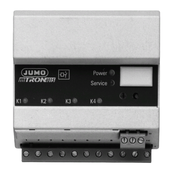
Page 10: Anzeige- Und Bedienelemente
Systemhandbuch Teil 1 70.4000 „Allgemeines“ Schalter (Abschlußwiderstand) v Kapitel 4.6 „LON-Abschlußwiderstand“ Installations-Taste Anmeldung des Moduls in der Projektierungssoftware JUMO mTRON-iTOOL Setup-Schnittstelle für die Setup-Interfaceleitung, welche das Modul mit dem PC verbindet. Bei angeschlossener Setup-Interfaceleitung erfüllt das Mo- dul nur noch die Funktion eines PC-LON-Schnittstellenum- setzers. -
Page 11: Elektrischer Anschluß
4 Elektrischer Anschluß 4.1 Installationshinweise Sowohl bei der Wahl des Leitungsmaterials, bei der Installation als auch beim elektrischen Anschluß des Moduls, sind die Vorschriften der VDE 0100 „Bestimmungen über das Errichten von Starkstroman- lagen mit Nennspannungen unter 1000V“ bzw. die jeweiligen Landes- vorschriften zu beachten. -
Page 12: Galvanische Trennung
4 Elektrischer Anschluß Neben einer fehlerhaften Installation können auch falsch eingestellte Werte am Modul den nachfolgenden Prozeß in seiner ordnungsgemä- ßen Funktion beeinträchtigen. Es sollten daher immer vom Modul un- abhängige Sicherheitseinrichtungen, z. B. Überdruckventile oder Temperaturbegrenzer/-wächter vorhanden und die Einstellung nur dem Fachpersonal möglich sein. -
Page 13: Geeignete Leitungen
4 Elektrischer Anschluß 4.3 Geeignete Leitungen LON- Schirmung Schnittstelle Als Verbindungsleitung wird eine abgeschirmte verdrillte Zweidrahtleitung (Twisted Pair) empfohlen. Die Schirmung muß an die Technische Erde (TE) der LON-Schnittstelle ange- schlossen werden. Leitungstypen Struktur Leitungsquerschnitt Leitungslänge (max.) Linie 1,4 mm (AWG 16) 2700m 0,34mm... -
Page 14: Anschlußplan
4 Elektrischer Anschluß 4.4 Anschlußplan Modulunterseite mit steckbaren Schraubklemmleisten Klemmleiste II Klemmleiste I Der elektrische Anschluß Die Spannungsversorgung muß mit darf nur von Fachpersonal der auf dem Typenschild angege- durchgeführt werden! benen Spannung übereinstimmen. Klemmleiste I Anschluß für Anschlußbelegung Bemerkungen Symbole Ausgänge Ausgang 1... - Page 15 4 Elektrischer Anschluß Steckbare Klemmleiste II Anschluß für Anschlußbelegung Bemerkungen Symbol LON-Schnittstelle II_13 = TE Abschirmung II_14 = Net_A Polarität II_15 = Net_B beliebig...
-
Page 16: Netzwerkanschluß
4 Elektrischer Anschluß 4.5 Netzwerkanschluß Es handelt sich beim JUMO mTRON-Automatisierungssystem um das Feld- bus-Netzwerkkonzept mit dem Namen LON ( ocal perating etwork). Als Übertragungsleitung wird eine abgeschirmte verdrillte Zweidraht-Leitung (Twisted Pair) verwendet. Als Verdrahtungsmöglichkeiten stehen Linien-, Ring- , Stern- oder gemischte Struktur (Free Topology) zur Auswahl: Linienstruktur Die physikalischen Enden werden beidseitig mit einem Abschlußwiderstand... - Page 17 4 Elektrischer Anschluß Sternstruktur Der Abschlußwiderstand eines beliebigen Modules im Stern muß auf 50Ω ein- gestellt werden. v Kapitel 4.6 „LON-Abschlußwiderstand“ Gemischte Struktur Der Abschlußwiderstand eines beliebigen Modules muß auf 50Ω eingestellt werden. v Kapitel 4.6 „LON-Abschlußwiderstand“...
-
Page 18: Lon-Abschlußwiderstand
4 Elektrischer Anschluß 4.6 LON-Abschlußwiderstand Die Schalter für den Abschlußwiderstand des LON-Netzwerkes befindet sich auf der Modulfrontseite links unterhalb des Setup-Steckers hinter der Gehäu- seöffnung. h Mit Schraubendreher, oder Kugelschreiber, die Schalter in gewünschte Stellung bringen... - Page 20 M. K. JUCHHEIM GmbH & Co Hausadresse: Moltkestraße 13 - 31, 36039 Fulda, Germany Lieferadresse: Mackenrodtstraße 14, 36039 Fulda, Germany Postadresse: 36035 Fulda, Germany Telefon: (06 61) 60 03-0 Telefax: (06 61) 60 03-5 00 E-Mail: mail@jumo.net Internet: www.jumo.de...
- Page 21 Relay module B 70.4015.4 Installation Instructions 8.99...
- Page 23 Contents Introduction Preface ........................3 Delivery package ....................3 Typographical conventions ................... 4 Type designation ....................5 Installation Location and climatic conditions ................. 6 Dimensions ......................6 Mounting the module on a standard rail .............. 6 Removing the module .................... 7 Displays and controls Electrical connection Installation notes ....................
-
Page 25: Introduction
OEM (original equipment manufacturer) and to the user with appropriate technical know-how. It describes the scope of delivery of the JUMO automation system with its modules, and gives all the necessary infor- mation for project design and start-up. -
Page 26: Typographical Conventions
1 Introduction 1.3 Typographical conventions Warning signs The signs of Danger and Warning are used in these Installation Instructions under the following conditions: Danger This symbol is used when there may be danger to personnel if the instructions are disregarded or not followed accurately. Warning This symbol is used when there may be damage to equipment or data if the instructions are disregarded or not followed accurately. -
Page 27: Type Designation
1 Introduction 1.4 Type designation The type code contains all factory-configured settings of the outputs (1) and the supply (2). The supply voltage must correspond to the voltage shown on the label. The label is affixed to the housing. 704015/0- ... - .. (1) Outputs Standard version .............. -
Page 28: Installation
2 Installation 2.1 Location and climatic conditions The module is suitable for mounting on standard rails 35 mm x 7.5 mm to EN 50 022 inside a control cabinet. The protection class is IP20 (EN 60 529). The ambient temperature at the location can be 0—50°C at a relative humidity not exceeding 80%, no condensation. -
Page 29: Removing The Module
2 Installation 2.4 Removing the module Switch off the supply! h Pull off connectors I and II (1) h Insert screwdriver into the release lug on the underside of the module and lever it upwards (2). The housing can be swung out towards the front (3). -
Page 30: Displays And Controls
System Manual Part 1 70.4000 “General” Switches (termination resistance) v Section 4.5 “LON termination resistance” Installation key the module reports to the JUMO mTRON-iTOOL project design software Setup interface for the setup interface lead which links the module to the PC. -
Page 31: Electrical Connection
4 Electrical connection 4.1 Installation notes The choice of cable, the installation and the electrical connection of the module must meet the requirements of VDE 0100 “Regulations on the Installation of Power Circuits with nominal voltages below 1000V” or the appropriate local regulations. Work on the module must only be carried out to the extent described and, like the electrical connection, only by properly qualified personnel. -
Page 32: Isolation
4 Electrical connection Apart from unsatisfactory installation, incorrect settings on the modu- le may interfere with the proper operation of the subsequent process. Provisions should therefore always be made for safety devices inde- pendent of the module, e.g. overpressure valves or temperature li- miters/monitors. -
Page 33: Suitable Leads
4 Electrical connection 4.3 Suitable leads LON interface Screen A screened twisted pair is recommended as a transmission line. The screen must be connected to the technical earth (TE) of the LON interface. Lead types Structure Conductor cross-section max. lead length Line 1.4 mm (16 AWG) -
Page 34: Connection Diagram
4 Electrical connection 4.4 Connection diagram Module underside with plug connectors Connector II Connector I electrical connection The supply must correspond to the must only be carried out by voltage specified on the label. properly qualified personnel! Connector I Connection for Terminals Notes Diagram... - Page 35 4 Electrical connection Plug-in connector II Connection for Terminals Notes Diagram LON interface II_13 = TE Screen II_14 = Net_A II_15 = Net_B polarity...
-
Page 36: Network Connection
4 Electrical connection 4.5 Network connection The JUMO mTRON automation system incorporates the fieldbus network concept called LON ( ocal perating etwork). A screened twisted pair is used as a transmission line. The connection can be made as line, ring, star or mixed structure (free topology). - Page 37 4 Electrical connection Star structure The termination resistances of any one module in the star must be set to 50Ω. v Section 4.6 “LON termination resistance” Mixed structure The termination resistance of any one module must be set to 50Ω. vSection 4.6 “LON termination resistance”...
-
Page 38: Lon Termination Resistance
4 Electrical connection 4.6 LON termination resistance The switches for the termination resistance of the LON network are located at the front of the module, left underneath the setup plug, behind the housing opening. h Using a screwdriver or a ball-point pen, position the switches as required. - Page 40 M.K. JUCHHEIM GmbH & Co. United Kingdom 36035 Fulda JUMO Instrument Co. Ltd. JUMO PROCESS CONTROL INC. Germany Temple Bank, Riverway 735 Fox Chase, Phone ++49 6 61-60 03-0 GB-Harlow, Coatesville, PA 19320 ++49 6 61-60 03-6 07 Essex CM20 2TT...
Need help?
Do you have a question about the mTRON B 70.4015.4 and is the answer not in the manual?
Questions and answers