
Related Manuals for Waterstone 5500


Summary of Contents for Waterstone 5500
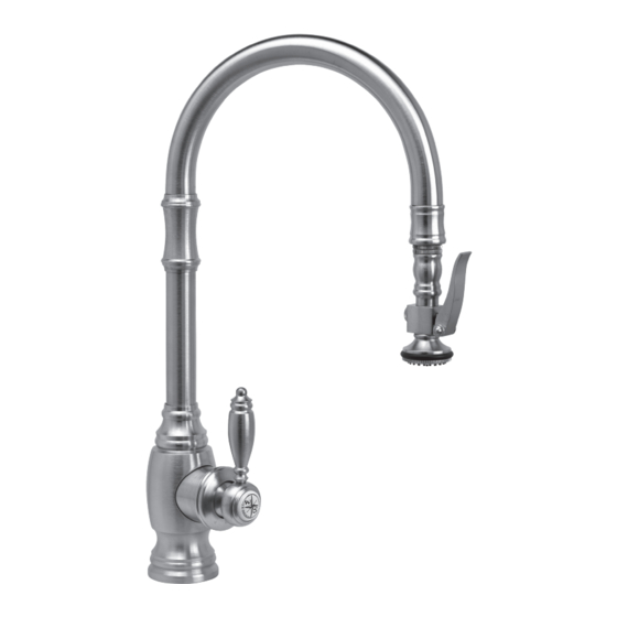
- Page 1 TRADITIONAL PLP PULLDOWN FAUCET INSTALLATION INSTRUCTIONS Model #s: 5500, 5600, 5610, 5200, 5210 5500 5600 5610 5200 5210...
- Page 2 HANDLE POSITION HANDLE POSITION Waterstone faucets are designed to be installed in 3 different faucet positions. Choose to have the handle on left, front or right. Your faucet is factory configured for the most common positions - a front and right side installation.
- Page 3 (F) clockwise or right (Fig. 1). Waterstone gives you the option of adjusting to increase or counterclockwise to the handle 45 degrees to avoid hitting backsplash.
- Page 4 CLEANING DEBRIS SCREEN CLEANING DEBRIS SCREEN CLEANING AERATOR CLEANING AERATOR 1. Turn off water supplies underneath sink and remove any water pressure by opening the faucet handle. 2. Unscrew sprayer (A) from spray hose by holding knurled swivel (B). 3. Inspect, remove and clean debris screen (C) in sprayer.
- Page 5 INSTALL SOAP/LOTION DISPENSER (OPTIONAL) INSTALL SOAP/LOTION DISPENSER (OPTIONAL) 1-3/8” HOLE Pull and remove spout (A) from dispenser body (B). Remove COUNTER clamp nut (C) from OR SINK threaded shroud (D). Fit dispenser body through 1-3/8” hole on counter or sink. (No plumbers putty is required.
- Page 6 GARBAGE DISPOSAL Slide other end of tubing (F) into tube Plug control box into undersink fitting at bottom of Tighten clamp screws (E) Hand tighten switch base back electrical outlet. Plug garbage securely with screwdriver. down to cover threads. control box (G). disposal into either dual outlet.
- Page 7 INSTALL DUAL PORT AIR GAP (OPTIONAL) INSTALL DUAL PORT AIR GAP (OPTIONAL) 1-1/2” HOLE Slide gasket down and screw top clamp nut back onto piping. Pull air gap (A) off of upper cap Unscrew and remove top clamp From underneath counter Adjust the two clamp nuts to nut (B).
Need help?
Do you have a question about the 5500 and is the answer not in the manual?
Questions and answers