Table of Contents
Advertisement
Available languages
Available languages
Quick Links
Advertisement
Chapters
Table of Contents

Related Manuals for SPM U-go


Summary of Contents for SPM U-go
- Page 1 U-go Versione a pompa Pump version Ausführung mit Pumpe Manuale d’uso e manutenzione Pag.2 Operator’s manual Page 25 Betriebs- und Wartungsanleitung Seite 54 Data di emissione: Marzo, 2016 Revisione: 2 Pag. : 1/80...
- Page 2 Revisione: 02 © 2016 – SPM Drink Systems Tutti i diritti di riproduzione del presente manuale sono riservati alla SPM DRINK SYSTEMS, la riproduzione anche parziale è vietata. Le descrizioni e le illustrazioni sono riferite alla specifica macchina/impianto in oggetto. SPM DRINK SYSTEMS si riserva il diritto di apportare in qualsiasi momento tutte le modifiche che riterrà...
-
Page 3: Table Of Contents
INDICE 1. AVVERTENZE E CONSIGLI IMPORTANTI ..............4 2. CORREDO DELL’APPARECCHIO ....4 3. INDICAZIONI UTILI PER IL TRASPORTO4 4. INDICAZIONI UTILI PER IL SOLLEVAMENTO ........4 5. SPECIFICHE TECNICHE ......5 6. POSIZIONAMENTO ........6 7. COLLEGAMENTO ALLA RETE ELETTRICA ..........7 8. OPERAZIONI D’AVVIAMENTO E MODALITA’... -
Page 4: Avvertenze E Consigli Importanti
installato in luoghi dove possa essere 1. AVVERTENZE E CONSIGLI controllato da personale qualificato. Non posizionare bombole con gas infiammabile IMPORTANTI vicino a questa apparecchiatura. Questa apparecchiatura è stata progettata Il presente manuale d’uso ed installazione per applicazioni quali: è parte integrante dell’apparecchio e dovrà Aree cucina per staff in negozi, uffici essere conservato per qualsiasi o altri ambienti lavorativi;... -
Page 5: Specifiche Tecniche
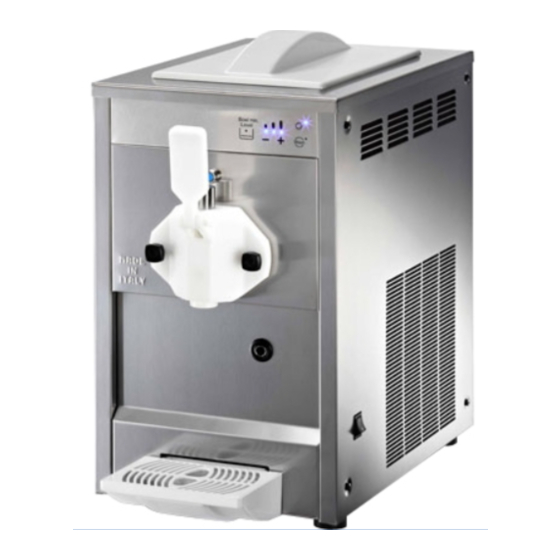
Le dimensioni di ingombro dell’ apparecchio Attenzione sono: Non sollevare mai l’apparecchio singolarmente, ma con l’aiuto di un altro U-go operatore. • Altezza 60 cm. • Larghezza 35.7 cm. Per non provocare danni all'apparecchio, le • Profondità 52.1 cm. manovre di carico e scarico sono da effettuarsi •... -
Page 6: Posizionamento
Importante La messa a terra è necessaria e obbligatoria a 6. POSIZIONAMENTO termine di legge. Prima di effettuare qualsiasi operazione di pulizia o manutenzione L'installazione e le successive operazioni di straordinaria assicurarsi di aver scollegato manutenzione, devono essere effettuate da l’apparecchio dalla rete togliendo la spina di personale specializzato ed addestrato alimentazione. -
Page 7: Collegamento Alla Rete Elettrica
7. COLLEGAMENTO ALLA RETE ELETTRICA SOLO PER MANUTENTORE Prima di inserire la spina nella presa di alimentazione, come già spiegato nel paragrafo precedente, è necessario che per la Vostra sicurezza prendiate attenta visione delle seguenti precauzioni: - Accertarsi che il collegamento sia effettuato ad un impianto dotato di un efficace messa a terra come previsto dalle vigenti normative di sicurezza (fig.3). -
Page 8: Operazioni D'avviamento Emodalita' D'uso
8. OPERAZIONI D’AVVIAMENTO E MODALITA’ D’USO !ATTENZIONE! PRIMA DI EFFETTUARE IL PRIMO AVVIAMENTO DELLA MACCHINA, PROCEDERE ALLE OPERAZIONI DI PULIZIA E SANITIZZAZIONE DESCRITTE NEL CAPITOLO 9 - Diluire e miscelare, in un recipiente a parte, il prodotto con acqua o latte secondo le indicazioni Fig. - Page 9 - Versare 1.5 litri di prodotto nella vasca superiore (fig.8) ed attendere che defluisca all’interno del cilindro di congelamento. Fig. 8 - Regolare la leva di afflusso aria sulla posizione desiderata ruotandola in senso anti orario per aumentare l’overrun del prodotto ed in senso orario per diminuirlo (fig.
- Page 10 - Posizionare la staffa di fissaggio per il tubo di pressione della pompa come indicato in figura - Versare il prodotto rimanente nella vasca superiore. - Riposizionare il coperchio sulla vasca, inserire la spina ed attivare l’interruttore generale A (fig.13). - Selezionare la modalità...
- Page 11 - Una volta che il prodotto avrà raggiunto la consistenza desiderata i LED smetteranno di lampeggiare e la rotazione delle coclea verrà interrotta. - Per erogare, posizionare il bicchiere sotto al rubinetto e tirare la leva come mostrato in figura 16, la coclea inizierà a ruotare di nuovo facilitando così...
-
Page 12: Operazioni Di Pulizia Esanitizzazione Quotidiana
9. OPERAZIONI DI PULIZIA E SANITIZZAZIONE QUOTIDIANA Né la casa costruttrice della macchina, né il Al fine di avere sempre un buon funzionamento quella produttrice del preparato alimentare dell’apparecchio e di rispettare le vigenti introdotto nella stessa, possono essere ritenute normative sanitarie, è... - Page 13 - Disattivare l’impianto frigorifero spingendo il tasto accensione/spegnimento B. - Attivare la modalità lavaggio spingendo il relativo tasto C. - Munirsi di un comune prodotto adatto alla disinfezione di oggetti in acciaio inox, plastica e gomma (AMUCHINA®). IMPORTANTE Attenersi in maniera scrupolosa alle Fig.
- Page 14 - Rimuovere la pompa ruotandola prima in senso orario e poi tirandola verso il centro della vasca in modo da staccarla dal suo albero di supporto (fig.22). - Una volta rimosso il tubo è possibile svuotare il cilindro di congelamento da tutto il prodotto residuo.
- Page 15 Attenzione Onde evitare rischi di shock elettrico o di contatto con parti mobili, durante le operazioni di smontaggio e rimontaggio, assicurarsi che tutti gli interruttori siano nella posizione off e che il cavo di alimentazione sia scollegato dalla rete. - Disattivare l’interruttore generale A posto sul lato destro della macchina e disconnettere il Fig.
- Page 16 - Rimuovere il dispositivo per dare la forma a stella al gelato dalla flangia (fig.31). - Estrarre la spirale di miscelazione e tutti i componenti ad essa assemblati (fig.32). Fig. 31 - Scomporre la spirale come indicato in figura 33 e 30 avendo cura di rimuovere tutti i componenti indicati in seguito: •...
- Page 17 - Rimuovere dalla vasca superiore tutti i componenti ancora presenti al suo interno e indicati in figura 35: E – galleggiante livello prodotto; G – girante mescolamento. - Lavare accuratamente ciascuno di questi componenti con acqua calda e detersivo per stoviglie.
- Page 18 - Qualora la macchina ne sia provvista, pulire il tubo scarico frontale con lo scovolino dato a corredo con la macchina oppure rimuovere il cassettino laterale come indicato in figura 38 e verificare che non sia presente alcuna traccia di sgocciolamento avendo poi cura di inserire di nuovo il cassettino.
- Page 19 - Rimontare tutti i componenti delle spirale avendo cura di rispettare i versi corretti come mostrato in figura 39 e 40; tali componenti sono: • L’albero centrale L (fig.39); • I due pattini raschiatori N (fig.39); • Le due tenute posteriori M ed O avendo cura di inserire prima quella con la boccola grigia in metallo (M) e quindi quella con la boccola bianca in plastica...
- Page 20 - Una volta assemblata, inserire la spirale con cura nel cilindro facendo in modo che il codolo posteriore entri perfettamente nella sua sede all’interno del cilindro (fig.42). !ATTENZIONE! Durante l’inserimento della spirale all’interno del cilindro afferrare entrambi i pattini come indicato in figura 42 in modo da mantenerli in posizione durante l’inserimento.
- Page 21 - Una volta inserita correttamente la flangia, fissarla con i suoi pomelli avvitandoli a fondo (fig.46). - Una volta rimontati tutti i componenti del cilindro congelatore, sistemare tutti i componenti del serbatoio superiore nella stessa posizione che occupavano prima della sanitizzazione (vedi figura 47).
-
Page 22: Manutenzione Straordinaria
10. MANUTENZIONE STRAORDINARIA Attenzione Prima di procedere a qualsiasi operazione di manutenzione, è obbligatorio spegnere l’apparecchio e staccare il cavo di alimentazione dalla presa di corrente. Pulizia del condensatore Al fine di garantire un buon rendimento dell’impianto frigorifero, è indispensabile effettuare una buona pulizia del condensatore almeno una volta al mese od ogniqualvolta il livello di intasamento lo imponga. -
Page 23: Controllo E Sostituzione Delle Guarnizioni
Controllo e sostituzione delle guarnizioni Stoccaggio invernale GUARNIZIONE FLANGIA FRONTALE Per proteggere la macchina durante i periodi di inattività come l’inverno, è importante La guarnizione posta sulla flangia frontale va immagazzinarla correttamente come descritto in sostituita ogni 6 mesi a seconda dello stato di seguito: usura e del livello di manutenzione e lubrificazione. -
Page 24: Informazioni Utili Sui Preparati Per Gelato
11. INFORMAZIONI UTILI SUI 12. ESCLUSIONE DI RESPONSABILITA’ PREPARATI PER GELATO La casa costruttrice declina ogni forma di responsabilità per eventuali danni che possono direttamente o indirettamente derivare a AUMENTO DI VOLUME persone, cose, animali in conseguenza della mancata osservanza di tutte le prescrizioni Durante il passaggio dallo stato liquido iniziale a indicate nel presente manuale e concernenti quello denso e cremoso finale, il prodotto... -
Page 25: Guida Alla Risoluzione Dei Problemi
13. GUIDA ALLA RISOLUZIONE DEI NOTA BENE: le seguenti procedure PROBLEMI devono essere eseguite da un tecnico qualificato Problema Possibile causa Soluzione • • macchina Lo spazio di ventilazione attorno Lasciare almeno 20cm di spazio libero raffredda raffredda alla macchina è inadeguato attorno alla macchina e non posizionarla •... - Page 26 Problema Possibile causa Soluzione • • Lampeggiano il LED del Motore bloccato Prodotto troppo denso, attendere 30 • tasto quello Sonda vasca staccata minuti e riavviare con consistenza più • consistenza 3 Sonda vasca in corto circuito bassa • Sostituire sonda •...
- Page 27 (protected in a transparent and waterproof cover to avoid deterioration) and must accompany the machine throughout its life, including any changes of ownership. In case of loss or damage, it is possible to request a copy from SPM DRINK SYSTEMS, reporting the data shown on the identification plate SPM DRINK SYSTEMS declines any responsibility for improper use of the machine/equipment and/or for damage caused by operations not provided for in this manual.
- Page 28 TABLE OF CONTENTS 1. IMPORTANT WARNINGS AND ADVICE29 2. SUPPLIED WITH THE APPLIANCE ..29 3. ADVICE FOR TRANSPORT .....29 4. ADVICE FOR LIFTING ......29 5. TECHNICAL SPECIFICATIONS ....30 6. POSITIONING ..........31 7. CONNECTING TO MAINS POWER SUPPLY .............32 8. START-UP PROCEDURES AND METHOD OF USE ............33 9.
-
Page 29: Supplied With The Appliance
Common areas in hotels, motels and 1. IMPORTANT WARNINGS AND other residential environments Bed and breakfast, catering and ADVICE similar applications This operator's and installation manual is an integral part of the appliance and 2. SUPPLIED WITH THE APPLIANCE should be kept for future consultation. Unless otherwise stated, this manual is At the time it is opened, inside the packaging intended for the operator (staff using the... -
Page 30: Technical Specifications
To avoid damage to the appliance, loading and U-go • unloading operations should be carried out with Height 60 cm • particular care. It is possible to lift the appliance Width 35.7 cm • with forklifts, motorised or manual, placing the Depth 52.1 cm... -
Page 31: Positioning
6. POSITIONING FOR MAINTENANCE STAFF ONLY Installation and subsequent maintenance operations must be carried out by staff qualified and trained in the use of the appliance in accordance with the regulations in force. a) After removing the packaging, preserve all parts of it for winter storage and ensure the integrity of the appliance (fig. -
Page 32: Connecting To Mains Power Supply
7. CONNECTING TO MAINS POWER SUPPLY FOR MAINTENANCE STAFF ONLY Before inserting the plug into the power socket, as already explained in the previous section, it is necessary that you carefully read the following instructions for your own safety: - Make sure the connection is made to a system with an effective earth as required by current safety standards (fig. -
Page 33: Start-Up Procedures And Method Of Use
8. START-UP PROCEDURES AND METHOD OF USE !ATTENTION! BEFORE STARTING THE APPLIANCE THE FIRST TIME, CARRY OUT THE CLEANING AND SANITISING PROCEDURES DESCRIBED IN CHAPTER 9. - Dilute and mix the preparation in a separate container according to the manufacturer’s Fig. - Page 34 - Pour 1.5 litres of mix into the top tank (fig. 8) and wait for it to flow into the freezing cylinder. Fig. 8 - Lubricate the two o-ring of the compression pipe and insert their side into the freezing cilinder connection hole (fig.
- Page 35 - Place the fixing bracket on the pump pressure pipe (fig.12). - Pour the remaining product into the upper tank. - Replace the cover on the tank, insert the plug and turn on the main switch A (fig. 13). - Select the desired mode of operation from the control panel (fig.
- Page 36 - Once the product has reached the desired consistency the LEDs will stop flashing and the rotation of the beater will stop. - To dispense, place a glass under the tap and pull the lever as shown in fig. 16. The beater will begin to rotate again, starting the dispensing phase.
-
Page 37: Daily Cleaning And Sanitising
9. DAILY CLEANING AND SANITISING Neither the manufacturer of the appliance, nor In order that the appliance always functions the producer of the food preparation introduced correctly and to comply with the applicable into it, shall be held liable for any damage that hygiene regulations, it is essential to carry out may directly or indirectly occur to persons as a the procedures for cleaning and sanitising... - Page 38 - Switch off the cooling system by pushing power button B. - Activate cleaning mode pushing the corresponding button C. - Use a common product suitable for sanitising stainless steel, plastic and rubber objects (such as AMUCHINA® in Italy). IMPORTANT: Fig.
- Page 39 - Remove the pump by first rotating it counter- clockwise and then by pulling it towards the upper tank centre in order to disassemble it from its shaft (fig. 22). - Once removed the pressure pipe is possible to empty the remaining product from the freezing cylinder using the dispenser lever until nothing further comes out.
- Page 40 Attention To avoid risk of electrical shock or contact with moving parts during dismantling and reassembly, make sure all switches are in the off position and that the power lead is disconnected from the mains. - Turn off the main switch A on the right side of the appliance and disconnect the power lead from the mains.
- Page 41 - Remove the device that gives the star-shaped form to the ice cream from the flange (fig. 31). - Extract the beater and all components mounted on it (fig. 32). Fig. 31 - Dismantle the beater as shown in fig. 33 and 30, taking care to remove all the components listed below: •...
- Page 42 - Remove all components inside the top tank as shown in fig. 35: E – floating product level; G – mixing impeller. - Wash each of these components thoroughly with hot water and washing-up liquid. - Remove the drip tray by pulling it gently Fig.
- Page 43 - In case the machine is provided with the front side discharge pipe, clean it with the brush supplied with the appliance, otherwise remove the side drawer as indicated in figure 38 and check for some dripping remembering to reinsert it once checked. Attention The machine is provided with a left side drawer to collect some dripping from the...
- Page 44 - Reassemble all the components of the beater, taking care to observe the correct alignment as shown in fig. 39 and 40. These components are: • Central shaft L (fig.39); • Two scrapers N (fig.39); • The two rear seals M and O taking care to insert first the one with the metal grey bushing (M) and then the one with the white plastic bushing (O) as indicated in...
- Page 45 - Once assembled, insert the beater carefully into the cylinder making sure that the rear shank fits perfectly in its seat within the cylinder (fig. 42). !ATTENTION! During the insertion of the beater inside the cylinder grasp both the scrapers as shown in fig. 42 in order to keep them in position during the Fig.
- Page 46 - Once you have correctly mounted the flange, screw the security knobs right down (fig. 46). - Once all the components of the freezing cylinder have been refitted, place all components of the top tank in the same position they occupied before the sanitisation (fig. 47). - Place the fixing bracket back on the pump pressure pipe (fig.48).
-
Page 47: Extraordinary Maintenance
10. EXTRAORDINARY MAINTENANCE Attention Before carrying out any maintenance, you must switch off the appliance and unplug the power lead from the socket. Cleaning the condenser In order to ensure good performance of the cooling system, it is essential to clean the condenser at least once a month, or whenever the level of clogging necessitates it. -
Page 48: Checking And Replacing The Seals
Checking and replacing the seals Winter storage BEATER AND FLANGE SEAL To protect the appliance during periods of inactivity such as winter, it is important to store The front side flange seal should be replaced it properly as described below: every 6 months depending on the state of wear and the level of maintenance and lubrication. -
Page 49: Useful Information On Ice Cream Mixes
11. USEFUL INFORMATION ON ICE 12. DISCLAIMER CREAM MIXES The manufacturer declines any liability for damage that may occur directly or indirectly to persons, property and animals as a result of VOLUME INCREASE failure to observe all the instructions given in this manual and especially the warnings During the transition from the initial liquid state concerning installation, use and maintenance of... -
Page 50: Troubleshooting Guide
NOTE: The following procedures must 13. TROUBLESHOOTING GUIDE be performed by qualified technical staff Problem Possible cause Solution • • The appliance does not The space around the appliance is Allow at least 20 cm of free space around cool, cools only inadequate for ventilation... - Page 51 Problem Possible cause Solution • • The LEDs for the ON Motor blocked Product consistency too high, turn off, button and consistency wait 30 minutes and turn on again with a • level 3 flash Tank probe detached lower consistency level •...
- Page 52 Revision: 02 © 2016 – SPM Drink Systems Alle Rechte auf Vervielfältigung des vorliegenden Handbuchs sind der Fa. SPM DRINK SYSTEMS vorbehalten. Die auch nur teilweise Vervielfältigung ist untersagt. Die Beschreibungen und Abbildungen beziehen sich auf die vorstehend genannte Maschine/Anlage. SPM DRINK SYSTEMS behält sich das Recht vor, an der Serienproduktion jederzeit alle Änderungen vorzunehmen, die sie für...
- Page 53 INHALT 1. WICHTIGE HINWEISE UND EMPFEHLUNGEN ........54 2. AUSSTATTUNG DES GERÄTS ....54 3. NÜTZLICHE HINWEISE FÜR DEN TRANSPORT ..........54 4. NÜTZLICHE HINWEISE FÜR DAS HEBEN ..............54 5. TECHNISCHE DATEN ......55 6. AUFSTELLUNG .........56 7. ANSCHLUSS AN DAS STROMNETZ ..57 8. INBETRIEBNAHME UND BETRIEBSMODALITÄTEN....58 9.
-
Page 54: Wichtige Hinweise Und Empfehlungen
Bed and Breakfast, Catering und ähnliche Anwendungsbereiche 1. WICHTIGE HINWEISE UND EMPFEHLUNGEN 2. AUSSTATTUNG DES GERÄTS Die vorliegende Betriebs- und Wartungsanleitung ist wesentlicher Bestandteil In der Verpackung müssen sich beim Öffnen die des Geräts und muss aufbewahrt werden, um folgenden Elemente befinden: sie auch in Zukunft jederzeit nachschlagen zu - die vorliegende Betriebs- und Wartungsanleitung können. -
Page 55: Technische Daten
Maschine zwischen 24 und 32°C. Um Schäden des Geräts zu vermeiden muss das Auf- Die Abmessungen des Geräts sind: und Abladen mit besonderer Sorgfalt vorgenommen werden. Das Gerät kann anhand eines motor-oder U-go • handbetriebenen Gabelstaplers gehoben werden. Höhe 60 cm •... -
Page 56: Aufstellung
Wichtig Die Erdung ist notwendig und gesetzlich 6. AUFSTELLUNG vorgeschrieben. Bevor Reinigungs- oder Wartungsarbeiten jeglicher Art vorgenommen Die Installation und spätere Wartung müssen werden, durch Abziehen des Steckers sicherstellen, von aufgrund der einschlägigen Vorschriften dass das Gerät von der Stromversorgung getrennt von Fachpersonal vorgenommen werden, das in ist. -
Page 57: Anschluss An Das Stromnetz
7. ANSCHLUSS AN DAS STROMNETZ NUR FÜR WARTUNGSTECHNIKER Bevor der Stecker in die Steckdose gesteckt wird, sind zu Ihrer eigenen Sicherheit wie bereits vorstehend erwähnt, sorgsam die folgenden Vorkehrungen zu treffen: - Sicherstellen, dass das Gerät an eine entsprechend den einschlägigen Sicherheitsvorschriften wirksam geerdete Elektroanlage angeschlossen wird (Abb. -
Page 58: Inbetriebnahme Und Betriebsmodalitäten
8. INBETRIEBNAHME UND BETRIEBSMODALITÄTEN !ACHTUNG! VOR DER ERSTEN INBETRIEBNAHME DER MASCHINE MÜSSEN ALLE IN KAPITEL 9 BESCHRIEBENEN REINIGUNGS- UND DESINFIZIERUNGSMASSNAHMEN GETROFFEN WERDEN - In einem Gefäß das Produkt je nach Angaben des Herstellers (siehe Abb. 4) mit Wasser oder Milch Abb. - Page 59 - 1.5 Liter Produkt in die obere Wanne geben (Abb.8) und abwarten, dass es in den Gefrierzylinder abläuft. Abb. 58 - Das Luftventil in die gewünschte Stellung bringen: durch Drehen gegen den Uhrzeigersinn erhöht sich der Overrun-Wert des Produkts, durch Drehen im Uhrzeigersinn verringert er sich (Abb.9).
- Page 60 - Den Befestigungsbügel der Druckleitung der Pumpe anbringen, wie in Abb. 12 dargestellt. - Das restliche Produkt in die obere Wanne gießen. - Den Deckel wieder auf der Wanne anbringen, den Stecker in die Steckdose stecken und den Hauptschalter A einschalten (Abb.13). - Die gewünschte Betriebsart am Bedienfeld einstellen (Abb.14) - Um die Kälteanlage auf Kühlbetrieb einzustellen, die...
- Page 61 - Wenn das Produkt die gewünschte Konsistenz erreicht hat hören die Leds auf zu blinken und die Rotation der Schnecke wird unterbrochen. - Zum Zapfen von Eis, einen Becher unter den Zapfhahn stellen und den Hebel ziehen, wie in Abbildung 16 dargestellt. Die Schnecke wird wieder in Betrieb gesetzt, um das Zapfen zu erleichtern.
-
Page 62: Tägliche Reinigung Und Desinfizierung
9. TÄGLICHE REINIGUNG UND DESINFIZIERUNG Weder der Hersteller der Maschine noch der Um eine stets einwandfreie Funktion des Geräts und Hersteller des eingefüllten Pulverprodukts können für die Einhaltung der einschlägigen Personenschäden verantwortlich gemacht werden, die Gesundheitsvorschriften zu gewährleisten, müssen direkt oder indirekt durch mangelnde Einhaltung der die nachstehend beschriebenen Reinigungs- und in diesem Handbuch angegebenen Vorschriften, Desinfektionsmaßnahmen häufig und sorgfältig... - Page 63 - Die Kälteanlage durch Drücken der Ein- /Ausschalttaste B abschalten. - Durch Drücken der Taste C die Spülfunktion einschalten. - Ein handelsübliches Produkt für die Desinfizierung von Gegenständen aus Kunststoff, Gummi und Edelstahl bereitstellen (z.B. AMUCHINA®). WICHTIG Die Anweisungen auf dem verwendeten Produkt in Bezug auf Zeit und Abb.
- Page 64 - Zum Entfernen die Pumpe zuerst im Uhrzeigersinn drehen und dann in Richtung der Wannenmitte ziehen, um sie von der Haltewelle zu lösen (Abb.22). - Nach dem Entfernen der Leitung kann das restliche Produkt vollständig aus dem Gefrierzylinder entfernt werden. - Nachdem die Maschine vollständig entleert wurde, die obere Wanne mit heißem Wasser füllen (Abb.23) und einige Minuten abwarten.
- Page 65 Achtung Um die Gefahr von Stromschlägen oder Kontakt mit den bewegten Maschinenteilen zu vermeiden, muss sichergestellt werden, dass während des Ein- und Ausbaus der Bauteile alle Schalter auf Off stehen und das Versorgungskabel aus der Steckdose gezogen ist. - Den Hauptschalter A auf der rechten Seite des Geräts abschalten und den Stecker aus der Steckdose Abb.
- Page 66 - Die Sternmatrize vom Flansch entfernen (Abb.31). - Die Mischerspirale und alle mit dieser verbundenen Bauteile herausziehen (Abb.32). - Die Spirale zerlegen, wie in Abb. 33 und 30 dargestellt, wobei darauf geachtet werden muss, dass Abb. 81 die nachstehend aufgeführten Teile entfernt werden: •...
- Page 67 - Aus der oberen Wanne alle noch darin befindlichen und in Abb. 35 angegebenen Bauteile entfernen: E – Schwimmer Produktfüllstand G – Mischrad - Alle diese Einzelteile sorgfältig mit heißem Wasser und Geschirrspülmittel reinigen. - Die Tropfschale leicht nach außen ziehen (Abb. 36), entfernen und sorgfältig mit heißem Wasser und Spülmittel reinigen.
- Page 68 - Sofern die Maschine damit ausgestattet ist, muss das frontale Ablassrohr mit der mitgelieferten Flaschenbürste gereinigt bzw. der seitliche Kasten herausgenommen werden, wie in Abb. 38 dargestellt. Prüfen, dass im Kasten keine Spuren von herausgetropftem Produkt vorhanden sind. Dann den Kasten sorgfältig wieder einsetzen.
- Page 69 - Alle Bauteile der Spirale wieder einbauen, wobei auf die richtige Reihenfolge zu achten ist. Siehe dazu Abbildung 39 und 40. Diese Bauteile sind: • Zentralwelle L (Abb.39) • Die beiden Abstreifer N (Abb.39) • Die beiden hinteren Dichtungen M und O. Darauf achten, dass zuerst die Dichtung mit der grauen Metallbuchse (M) und dann die Dichtung mit der weißen Kunststoffbuchse...
- Page 70 - Nachdem sie wieder zusammengesetzt wurde, die Spirale sorgfältig so in den Zylinder einsetzen, dass der hintere Schaft perfekt in seine Aufnahme im Inneren des Zylinders gleitet (Abb.42). !ACHTUNG! Beim Einsetzen der Spirale in den Zylinder beide Abstreifer fassen, wie in Abbildung 42 dargestellt, damit sie während des Einsetzens in der richtigen Lage bleiben.
- Page 71 -Nachdem der Flansch korrekt eingesetzt - Nachdem die vorstehend beschrieben Desinfektion wurde, müssen zur Befestigung die Handknöpfe sorgfältig vorgenommen wurde, ist die Maschine (Abb.46) bis zum Anschlag angezogen werden. gebrauchsbereit. - Wenn alle Bauteile des Gefrierzylinders wieder eingebaut sind, alle Teile der oberen Wanne in der gleichen Lage wieder einbauen, die sie vor der Desinfizierung hatten (siehe Abb.
-
Page 72: Ausserordentliche Wartung
AUSSERORDENTLICHE WARTUNG Achtung Bevor Wartungsarbeiten jeglicher Art ausgeführt werden, muss obligatorisch das Gerät abgeschaltet und der Stecker aus der Steckdose gezogen werden. Reinigung des Kondensators Um gute Leistungen der Kälteanlage zu gewährleisten muss der Kondensator mindestens einmal monatlich gereinigt werden, bzw. wenn er zu stark verstopft ist. -
Page 73: Kontrolle Und Austausch Der Dichtungen
Kontrolle und Austausch der Dichtungen Einlagerung über Winter DICHTUNG DES FRONTALEN FLANSCHS Um die Maschine bei Stillstandszeiten wie beispielsweise im Winter zu schützen, muss sie Die Dichtung am frontalen Flansch muss alle 6 ordnungsgemäß gelagert werden, wie nachstehend Monate ausgetauscht werden, je nach Verschleiß und beschrieben: Wartungs- bzw. -
Page 74: Nützliche Informationen Zur Herstellung Von Speiseeis
11. NÜTZLICHE INFORMATIONEN ZUR 12. HAFTUNGSAUSSCHLUSS HERSTELLUNG VON SPEISEEIS Der Hersteller verweigert jegliche Haftung für eventuelle direkte oder indirekte Personen-, Sach- und Tierschäden infolge der mangelnden Einhaltung VOLUMENSTEIGERUNG der Vorschriften dieses Handbuchs, insbesondere der Hinweise in Bezug auf Installation, Betrieb und Beim Übergang vom flüssigen Anfangszustand in den Wartung des Geräts. -
Page 75: Anleitung Zur Problem Lösung
HINWEIS: die nachstehenden 13. ANLEITUNG ZUR PROBLEM Arbeitsgänge müssen von LÖSUNG technischem Fachpersonal ausgeführt werden Problem Mögliche Ursache Abhilfe • • Die Maschine kühlt nicht Der Belüftungs-Freiraum rings um Mindestens 20 cm Freiraum rings um die oder nur teilweise, und die Maschine ist nicht ausreichend Maschine belassen und die Maschine fern •... - Page 76 Problem Mögliche Ursache Abhilfe • • Die LED der Taste ON Motor blockiert Produkt zu dickflüssig. Etwa 30 Minuten • und die Konsistenz-Led Sonde Wanne nicht abwarten, dann mit einem niedrigeren Nr. 3 leuchten angeschlossen Konsistenzwert neu starten • • Sonde der Wanne kurzgeschlossen Sonde austauschen •...
-
Page 77: Wiring Diagram
14. WIRING DIAGRAM Data di emissione: Marzo, 2015 Revisione: 1 Pag. : 77/80... - Page 78 Data di emissione: Marzo, 2015 Revisione: 1 Pag. : 78/80...
- Page 79 ASSISTENZA TECNICA ITALIA Mail: info@service-k.it Tel. 059782884 Conforme alla normativa RoHS Questo apparecchio è conforme alla direttiva europea 2002/95/CE e successive modifiche per quanto riguarda la restrizione all’uso di sostanze pericolose nella produzione di apparecchiature elettriche ed elettroniche. Smaltimento Ai sensi della direttiva RAEE 2002/96/CE e successiva modifica 2003/108/CE questa apparecchiatura viene contrassegnata con il seguente simbolo del contenitore di spazzatura con ruote barrato.
- Page 80 INTERNATIONAL CUSTOMER CARE intcustcare@spm-ice.it +39 059781761 Company with certified quality management system UN EN ISO 9001 Data di emissione: Marzo, 2015 Revisione: 1 Pag. : 80/80...
Need help?
Do you have a question about the U-go and is the answer not in the manual?
Questions and answers