Klein Tools MM600 Instruction Manual
Auto-ranging digital multimeter
Hide thumbs
Also See for MM600:
- User manual ,
- Instruction manual (57 pages) ,
- Instruction manual (62 pages)
Advertisement
Table of Contents
- 1 General Specifications
- 2 Electrical Specifications
- 3 Duty Cycle
- 4 Symbols on Meter
- 5 Symbols on Lcd
- 6 Feature Details
- 7 Function Buttons
- 8 "Range" Button
- 9 "Max/Min" Button
- 10 Resistance Measurements
- 11 Diode Test
- 12 Frequency / Duty-Cycle
- 13 Maintenance
- 14 Battery Replacement
- 15 Fuse Replacement
- 16 Customer Service
- Download this manual
Advertisement
Table of Contents

Subscribe to Our Youtube Channel
Related Manuals for Klein Tools MM600


Summary of Contents for Klein Tools MM600
- Page 1 MM600 ENGLISH INSTRUCTION MANUAL Auto-Ranging Digital Multimeter Digital Multimeter • DATA & RANGE HOLD • AUDIBLE CONTINUITY • MIN / MAX / RELATIVE • TEMPERATURE • DIODE TEST • CAPACITANCE & FREQUENCY 1000V...
-
Page 2: General Specifications
ENGLISH GENERAL SPECIFICATIONS Klein Tools MM600 is an automatically ranging digital multimeter that measures AC/DC voltage, AC/DC current, and resistance. It can also measure temperature, capacitance, frequency, duty-cycle, test diodes and continuity. • Operating Altitude: 6562 ft. (2000m) • Relative Humidity: <90% non-condensing •... -
Page 3: Electrical Specifications
ELECTRICAL SPECIFICATIONS VOLTAGE (AUTO-RANGING) Function Range Resolution Accuracy (50–60 Hz) 4.000V ±(1.0% + 5 digits) 40.00V 10mV ±(1.2% + 5 digits) AC Voltage (V AC) 400.0V 100mV ±(1.5% + 5 digits) 1000V 400.0mV 0.1mV ±(1.0% + 8 digits) 4.000V DC Voltage 40.00V 10mV ±(1.0% + 3 digits) -
Page 4: Duty Cycle
ENGLISH ELECTRICAL SPECIFICATIONS CAPACITANCE (AUTO-RANGING) Range Resolution Accuracy 40.00nF 10pF ±(5.0% + 35 digits) 400.0nF 0.1nF 4.000 F ±(3.0% + 5 digits) 40.00 F 10nF 400.0 F 100nF 1000 F ±(5.0% + 5 digits) Maximum Input: 600V DC or 600V AC RMS FREQUENCY (AUTO-RANGING) 9.999Hz 0.001Hz... - Page 5 ELECTRICAL SPECIFICATIONS OTHER MEASUREMENT APPLICATIONS Maximum Input: 600V DC or 600V AC RMS • Diode Test: 1.5 mA max, open circuit voltage 3.0V DC • Continuity Check: Audible signal when resistance <50Ω, max test current 0.35mA • Auto Power off: After ~30 minutes of inactivity •...
-
Page 6: Symbols On Meter
ENGLISH SYMBOLS ON METER AC/DC Voltage or Current Resistance (in Ohms) Audible Continuity Diode Capacitance Frequency Duty-cycle Double Insulated Class II Warning or Caution Risk of Electrical Shock Fuse (with rating below symbol) Warning or Caution To ensure safe operation and service of this meter, follow all warnings and instructions detailed in this manual. -
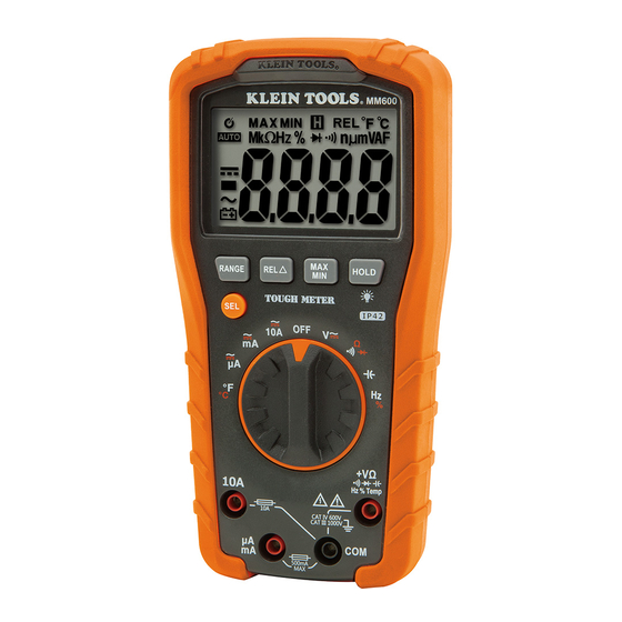
Page 7: Feature Details
FEATURE DETAILS NOTE: There are no user-serviceable parts inside meter. 4000 count LCD display "RANGE" button Function selector switch "REL" (Relative) button "10A" jack "MAX/MIN" button "COM" jack "HOLD" button "V " jack "SEL" (Select) button mA / µA jack... -
Page 8: Function Buttons
ENGLISH FUNCTION BUTTONS ON/OFF To Power ON the meter rotate the Function Selector switch from the OFF setting to any measurement setting. To Power OFF the meter rotate the Function Selector switch to the OFF setting. By default, the meter will automatically Power OFF after 30 minutes of inactivity. Reactivate meter by pressing any button. -
Page 9: "Max/Min" Button
FUNCTION BUTTONS "REL" (RELATIVE) BUTTON Relative measurements are available for Voltage, Current, Resistance, Temperature and Capacitance. 1. Perform first measurement. 2. With test leads connected, press REL to set frame of reference. 3. Perform second measurement. The value displayed is the difference between first and second measurements. - Page 10 ENGLISH OPERATING INSTRUCTIONS CONNECTING TEST LEADS Do not test if leads are improperly seated. Results could cause intermittent display readings. To ensure proper connection, firmly press leads into the input jack completely. INCORRECT CORRECT TESTING IN CAT III / CAT IV MEASUREMENT LOCATIONS Ensure the test lead shield is pressed firmly in place.
- Page 11 OPERATING INSTRUCTIONS AC/DC VOLTAGE (LESS THAN 1000V) 1. Insert RED test lead into V jack , and BLACK test lead into COM jack , and rotate function selector switch the V setting. NOTE: The meter defaults to AC measurement. Press the "SEL" button to toggle between AC and DC modes.
- Page 12 ENGLISH OPERATING INSTRUCTIONS • For AC/DC currents >400mA and <10A: Insert RED test lead into 10A jack , and BLACK test lead into COM jack , and rotate function selector switch to the 10A AC/DC setting. Red lead Black lead •...
- Page 13 OPERATING INSTRUCTIONS CONTINUITY 1. Insert RED test lead into V jack , and BLACK test lead into COM jack , and rotate function selector switch to the Continuity/Resistance/Diode setting. NOTE: The meter defaults to Continuity testing in this mode. Ensure that the Continuity Testing icon is visible on the display.
-
Page 14: Resistance Measurements
ENGLISH OPERATING INSTRUCTIONS RESISTANCE MEASUREMENTS 1. Insert RED test lead into V jack , and BLACK test lead into COM jack , and rotate function selector switch to the Continuity/Resistance/Diode setting. NOTE: The meter defaults to Continuity testing in this mode. To enter Resistance testing mode, press the "SEL"... -
Page 15: Frequency / Duty-Cycle
OPERATING INSTRUCTIONS CAPACITANCE 1. Insert RED test lead into V jack , and BLACK test lead into COM jack , and rotate function selector switch to the Capacitance setting. Display should read 0 nF with leads open. 2. Remove power from circuit. 3. - Page 16 ENGLISH OPERATING INSTRUCTIONS TEMPERATURE 1. Insert K-type thermocouple with adapter into the V and COM jacks (observe polarity markings on thermocouple and meter), and rotate function selector switch to the Temperature setting. NOTE: The meter defaults to Fahrenheit scale in this mode. To enter Celsius scale, press the "SEL"...
-
Page 17: Maintenance
MAINTENANCE BATTERY REPLACEMENT When indicator is displayed on LCD, batteries must be replaced. 1. Remove screw from battery/fuse door. 2. Replace 2 x AAA batteries (note proper polarity). 3. Replace battery/fuse door and fasten securely with screw. FUSE REPLACEMENT A fuse may blow if more than 500mA is applied to the A/mA jack or more than 10A is applied to the 10A jack . -
Page 18: Customer Service
ENGLISH CLEANING Be sure meter is turned off and wipe with a clean, dry lint-free cloth. Do not use abrasive cleaners or solvents. STORAGE Remove the batteries when meter is not in use for a prolonged period of time. Do not expose to high temperatures or humidity.
Need help?
Do you have a question about the MM600 and is the answer not in the manual?
Questions and answers