Table of Contents
Advertisement
Advertisement
Table of Contents

Related Manuals for KOMFI-RIDER Liberty


Summary of Contents for KOMFI-RIDER Liberty
- Page 1 MOBILITY SCOOTER USER MANUAL...
-
Page 2: Table Of Contents
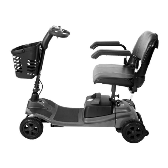
Congratulations on the purchase of your new Liberty Mobility Scooter! The advanced light-weight design of the Liberty with its superb leg room and streamline design ensures many years of enhanced trouble-free mobility. Correct use improves your mobility and quality of life. -
Page 3: Safety Guidelines
SAFETY GUIDELINES WARNING! An authorized Provider or qualified technician must perform the initial setup of this scooter and must perform all of the procedures in this manual. The symbols below are used throughout this owner's manual and on the scooter to identify warnings and important information. -
Page 4: Pre Ride Safety Check
PRE-RIDE SAFETY CHECK Get to know the feel of your scooter and its capabilities. We recommend that you perform a safety check before each use to make sure your scooter operates smoothly and safely. Perform the following inspections prior to using your Travel Scooter: ■... -
Page 5: Specification
SPECIFICATION Model Reference Liberty 12Ah Liberty Super 20Ah Speed (Max) 4 mph (6 km/h) 4 mph (6 km/h) Travel Range (Max)* 10 mi. (16 km)* 16 mi. (25 km)* Battery 2 x 12V 12Ah AGM 2 x 12V 20Ah AGM User Weight (Max) 21 st. -
Page 6: Components Of The Scooter
COMPONENTS OF THE SCOOTER Control Panel Freewheel Lever Seat Arm Pad Seat Post Retaining Screw Seat Splitting Pin/Knob Basket Anti-Tip Wheel Tiller Adjuster Knob Rear Wheel Tiler Lock Battery Gauge Seat Post Speed Adjustment Dial Front Wheel Key Switch Battery Charger Outlet Point Tiller Handle Battery Box Horn Button... -
Page 7: Operation - Control Panel
CONTROL PANEL 17. Battery Indicator/Gauge Tiller Handle 18. Speed Adjustment Dial Horn Button 19. Key Switch Throttle Lever Forward/Back Battery Indicator/Gauge: (17) Indicates the voltage of the batteries: Green – batteries are fully charged. Yellow – batteries are half full. ... -
Page 8: Operation - Scooter Assembly
Throttle Control Lever – Forward/Back: (22) This lever allows you to control the forward speed and the reverse speed of your scooter up to the maximum speed you pre-set with the speed adjustment dial. Place your right hand on the right hand tiller handle and your left hand on the left hand tiller handle: To move forward, use either of the following: ... - Page 9 TILLER ADJUSTMENT KNOB Loosen the tiller adjustment knob by tuning anti-clockwise - see below. Raise the tiller to the required position. Fully tighten the adjustment knob by turning clockwise making sure the tiller is securely positioned with the teeth fully engaged together. Tiller adjustment knob WARNING! Never operate the scooter unless the tiller is raised, the teeth are fully engaged and the tiller adjustment bolt fully tightened and securely positioned.
- Page 10 CONNECTING FRONT & REAR SECTIONS Connect the front and rear sections by aligning them and gently lifting the front section onto the two hooks of the rear section. (See Fig 6.3.1) Make sure the rear section is tipping back to allow the front section to lower into the correct position.
- Page 11 FITTING BATTERY BOX AND BASKET Carefully lower the battery box into position on the scooter making sure the box is securely and fully connected to the battery connector. (See Fig 6.5.1) Place basket onto bracket and make sure it is securely fixed. (See Fig 6.5.1) Fig 6.5.1 FITTING SEAT ...
- Page 12 FREEWHEEL LEVER The Freewheel lever on the scooter is located on the rear section of the scooter. Before driving the scooter needs to be put into the drive position. The two positions are: 1. Drive position - is indicated by ‘Closed’ - pull the lever backwards for this position. (Fig 6.7.1) 2.
-
Page 13: Operation - Scooter Disassembly
DISASSEMBLY OF YOUR SCOOTER The scooter disassembles into five main pieces: the basket, front section, rear section, seat and battery box as shown below: Basket Front Section Rear Seat Battery Box Section When disassembling or assembling your scooter, always make sure you have sufficient room to move the parts around. -
Page 14: Operation - Getting On Your Scooter
7.5 DISCONNECTING FRONT & REAR SECTIONS Lift the tiller splitter knob. (See Fig 7.5.1) The front and rear sections will then be disconnected. Fig 7.5.1 BEFORE GETTING ON TO YOUR SCOOTER Keep your batteries fully charged and avoid deeply discharging your batteries. ... - Page 15 GETTING ONTO YOUR SCOOTER 1. Make certain that the key is removed from the key switch. 2. Make sure the tiller is in the un-locked position. 3. Stand at the side of your scooter. 4. Disengage the seat rotation lever and rotate the seat until it is facing you. 5.
-
Page 16: Operation - Operating Your Scooter
OPERATING YOUR SCOOTER STARTING Make sure you are seated safely and properly on your scooter. Turn the speed adjustment dial fully anti-clockwise to the slowest setting. Insert the key into the key switch. Turn the key clockwise to the ‘’On’’ position. ... - Page 17 WARNING! Never descend or climb a gradient which is greater than the recommended maximum see 3.0 Specifications. WARNING! Never drive across (traverse) an incline, ramp etc, in any direction. WARNINIG! The anti-tip wheels are only effective on firm ground. They will sink into soft ground such as grass, snow or mud if the scooter rests on them.
-
Page 18: Operation - Getting Off Your Scooter
10.0 GETTING OFF YOUR SCOOTER 1. Bring your scooter to a complete stop. 2. Remove the key from the key switch. 3. Disengage the seat rotation lever and rotate the seat until you are facing toward the side of your scooter. - Page 19 11.2 CHARGING YOUR BATTERIES Make sure you read and understand the battery chargers user manual, if supplied, as well as the safety notes on the charger. Turn off the scooter power and remove the key Slide away the cover of the charger outlet point positioned on the front of the battery box as shown below: ...
- Page 20 WARNING! Risk of short circuit and electric shock if the battery charger has been damaged. Never use the charger if it has been dropped or damaged. WARNING! Risk of electric shock and damage to the batteries – Never attempt to recharge the batteries by attaching cables directly to the battery terminals.
-
Page 21: Emi
12.0 EMI / RFI The rapid development of electronics, especially in the area of communications, has saturated our environment with electromagnetic (radio) waves that are emitted by television transmitters, cellular phones, citizen’s band radios (CB’s), amateur radios (ham radios), wireless computer left, microwave transmitters, paging transmitters etc. -
Page 22: Daily Checking
13.0 DAILY CHECKING Check the following items before driving. If you find anything abnormal, contact your scooter dealer for a further inspection before using it. Item Inspection Content Is it tight? Handle bar Can they be turned left or right smoothly? Speed Dial Can it be adjusted freely and function well? Does the scooter move when the lever is engaged? -
Page 23: Basic Troubleshooting
15.0 BASIC TROUBLESHOOTING This table is only a guide to aid you in getting your scooter operating, should you have any problems. If you are unable to get your scooter operating, please contact your Scooter Dealer. Symptom Possible Solution Scooter does 1. -
Page 24: Flash Codes
16.0 FLASH CODES Scooter controller internal diagnostics The diagnostic flash codes for your scooter are designed to help you perform basic troubleshooting quickly and easily. A diagnostic flash code flashes from the Power light in the event one of the conditions listed below develops. FLASH FAULT EFFECT... - Page 25 17.0 WARRANTY RRANTY WARRANTY POLICY: LIMITED WARRANTY. IMPORTANT NOTICE – TO ENSURE THIS WARRANTY IS VALIDATED IT HAS TO BE COMPLETED AND RETURNED TO ONE REHAB WITHIN 14 DAYS OF PURCHASE 17.1 TWO-YEAR LIMITED WARRANTY Two years on all structural frame components; fork, seat post, and frame. Structural Frame Components, including Main Frame Fork...
-
Page 26: Warranty
17.4 WARRANTY EXCLUSIONS 1. ABS plastic shrouds and footrest covers (wear items are not warranted). 3. Tyres and Anti-tip Wheels (wear items are not warranted). 4. Upholstery and seating (wear items are not warranted). 5. Motor Brushes. 6. Brake Pads (wear items are not warranted). 7. - Page 27 THIS PAGE IS INTENTIONALLY BLANK...
Need help?
Do you have a question about the Liberty and is the answer not in the manual?
Questions and answers