
Related Manuals for Enso Avante Garde


Summary of Contents for Enso Avante Garde
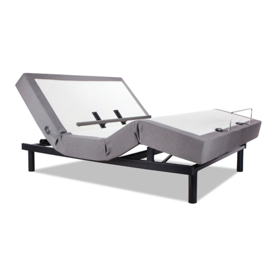
- Page 1 Avante Garde OWNER’S MANUAL Actual product appearance and functionality may vary from photographs, illustrations and descriptions included in this manual.
-
Page 2: Table Of Contents
table of contents Safety Precautions and Usage Statements ............... 1-3 Parts List . -
Page 3: Safety Precautions And Usage Statements
IN-HOME USE AND HOSPITAL STANDARDS: properly, or it has been dropped into water. Only use this bed base for Enso adjustable bed bases are designed solely for in-home use. This its intended use as described in this manual. Do not use accessories/ base was not designed as a hospital bed and is not designed to meet attachments that are not recommended by the manufacturer. - Page 4 TOLERANCE of the base creating a contact noise. When entering, exiting or shifting All Enso adjustable foundations, depending on make and model, are weight on the base, this contact noise may be audible as the wheels make designed and manufactured to perform and function within designated contact.
- Page 5 safety precautions and usage statements cycle. Attempting to circumvent or exceed this rating will shorten the BREAK IN PERIOD: life expectancy of the product and may void the warranty. The massage You can speed up the break-in period by simply spending time in the motors are not designed to operate continuously for more than 30 minutes adjustable bed through activities such as reading, watching TV or playing at a time.
-
Page 6: Parts List
parts list Before discarding the packing materials - ensure all the parts are accounted for. All electronics and components that need to be installed are located in boxes under the base or attached to the frame. Remote Control (1) Headboard Bracket Components: Mattress Retainer Bar Headboard Bracket... -
Page 7: Base Overview
base overview Lumbar Motor Head Massage Motor Head Motor USB Ports USB Ports Underbed Lighting Control Box Foot Motor Foot Massage Motor... -
Page 8: Remote Overview
remote overview REMOTE OVERVIEW ADJUST Lifts and Lowers Lumbar Support The HEAD arrows lift and lower the head section of the base. Lifts and Lowers Head Lifts and Lowers Foot The LUMBAR arrows Zero Gravity Customize the level of the lumbar Preset Position support. - Page 9 remote overview ONE TOUCH BUTTONS MASSAGE FEATURE One touch ZERO G preset The Head + and - buttons adjust ® position. Zero G adjusts your the head massage intensities. ® legs to a higher level than your heart helping to relieve pressure off the lower back and promote circulation.
-
Page 10: Quick Reference Guide
quick reference guide Not to scale. For illustration purposes only. Read all instructions before beginning installation. CONTROL BOX OVERVIEW ELECTRONICS OVERVIEW Head Massage- Motor Port Control Box Foot Massage- Motor Port Power Cord Lumbar Motor Split Cable Port Input Cord Foot Motor Port Power Supply... -
Page 11: Installation Guide
installation guide Always use two people when setting up the base. STEP 1 With the help of an able-bodied assistant, place the carton on the floor with the arrows pointing downwards. Remove the binding straps and packing materials, making sure not 3 inch leg to puncture the box with any sharp objects. - Page 12 installation guide STEP 6 STEP 9 Uncoil the Power Cord and connect to the Slide lumbar cross section (removed from underside of base) onto Power Supply. Place Power Supply on the the raised lumbar supports. ground and extend from the base. Ensure that the Power Supply and all attached cords are directed toward the desired surge protector.
-
Page 13: Power Down Box
installation guide power down box In the event that the base is stuck in an articulated po- STEP 11 sition during a power outage- the Power Down Box will Slide the left side of the mattress retainer bar into the bracket. Pull the retainer bar to the opposite bracket and secure the right return the base to a flat position. -
Page 14: Remote Pairing
pair remote The original remote that comes in the box is already paired to the bed base. No further action is required. In the event that the remote is not paired with the base, follow the steps below. STEP 1 STEP 3 Remove back cover from remote Press and hold button on the back of the... -
Page 15: Connecting Strap
connecting strap (optional) If a split setup is being installed, optional plastic connecting straps can be used to help secure the bases together. To purchase optional accessories, please call 1-844-534-3676. STEP 1 STEP 2 With the bases in their desired location, slightly loosen both legs to Slide side (a) of the connecting strap onto leg bolt. -
Page 16: Syncing Two Bases
syncing two bases (optional) A Sync Cord is included with Twin Long and Split King bases only. Not available on Queen, Full or Full-Long size bases. The Sync Cord connects the two control boxes to a single remote for the synchronization of two bases. STEP 1 STEP 4 Connect each power-down box male connection to the sync... -
Page 17: Headboard Brackets
headboard bracket installation guide A 9/16” (14 mm) & 1/2” (13 mm) socket and crescent wrench are necessary to complete installation. STEP 1 STEP 2 a.) Align the hole in the bracket to the brass sleeve into which the Attach the plastic spacer and T-Bracket. leg threads. -
Page 18: Troubleshooting
Plug bed base into a different electrical outlet, or test current outlet with another working appliance (a grounded, electrical surge protector is recommended). If issue is not resolved by following the instructions above, locate serial number on warranty card or back of remote and call Enso Customer Service: US 1-844-534-3676... -
Page 19: Español
Niveles 1-6 de la intensidad del masaje representan las revoluciones del motor por minuto. Enso bases ajustables de la cama están diseñados exclusivamente para su uso en el hogar. Esta base no fue diseñado como una cama de hospital y no está diseñado para cumplir con Nivel 6 proporciona el número máximo de RPM. - Page 20 No moje en exceso. Un cepillo de cerdas suaves se puede utilizar para eliminar la Todas las bases ajustables Enso, dependiendo de la marca y el modelo, están diseñados y fabricados para llevar a cabo y función dentro de los parámetros de control de calidad suciedad arraigada.
- Page 21 español espuma. Power Cord (1) = Cable de alimentación (1) Power Supply (1) = Fuente de alimentación (1) • Incline la base de su lado. Esto puede dañar las piernas y / o tornillos en las piernas. • Póngase de pie o saltar sobre la base ajustable en cualquier momento, esto puede Battery Backup Box (9 volt batteries not included) = Caja de la batería (baterías de 9 voltios no incluidas) dañar el chasis y motores.
- Page 22 español automáticamente. PASO 4: Si va a instalar una unidad de división. Activar el bloqueo de seguridad para niños Desenrosque el generador de corriente del marco y instale (2) pilas de 9 voltios (no incluidas). 1. Pulse el "Head Up" y "Masaje de pies Menos" botón o de forma simultánea o pulsando el Ponga el generador en el piso.
- Page 23 español están incluidos. No vincule ambas cajas de control con el mismo mando a distancia. RESUMEN Cada remoto debe tener una configuración de interruptor DIP diferente. Para uso de emergencia solamente, en caso de un corte de energía. Pg 15 - Guía de instalación del soporte cabecero En el caso de que la base se ha quedado atascado en una posición articulada durante un Un conector de 9/16 “y 1/2”...
- Page 24 MATÉRIAUX peut annuler la partie électrique de votre garantie. Des bases réglables Enso sont construits à partir de divers matériaux tels que le bois, les Animaux et enfants: métaux, les matières plastiques et des textiles. Tension, pression ou appliquée sur le châssis, la Jeter immédiatement les matériaux d'emballage, car il peut poser un risque d'étouffement...
- Page 25 Pour un nettoyage plus approfondi, les déversements de Toutes les bases réglables Enso, en fonction de la marque et le modèle, sont conçus et fab- liquides secs avec un chiffon propre et sec. Essuyez avec un chiffon propre humidifié avec de riqués pour exécuter et la fonction dans les paramètres désignés contrôle de la qualité.
- Page 26 français Battery Backup Box (9 volt batteries not included) = Batterie de secours Box Debout ou sauter sur la base réglable à tout moment, cela peut endommager le châssis et les moteurs. (piles 9 volts non inclus) Faites glisser la base pour le déplacer. Faire glisser la base pourrait endommager le cadre, Lumbar Support Round Tube (1) and wrenches (2) = Tube support lombaire ronde éplucher les secs / boulons, écrous ou casser vos jambes.
- Page 27 français Bouton Flash Light Massage des pieds Port Motor Zero Gravity Preset Position Lumbar Port Motor Ascenseurs et abaisse Pied Port Motor Régler Head Port Motor Le chef flèches haut / bas soulever et abaisser la section de tête de la base. Connecteur d'alimentation Le Lombaire flèches haut / bas de personnaliser le niveau de l'appui lombaire.
- Page 28 français augmenter le support lombaire à la position la plus haute et retirer les écrous et les attaches continu, puis tourner simultanément hors tension. de chaque support. Pg. 13 - Barrette de connexion (en option) Étape 9: Faites glisser section lombaire (retiré du dessous de la base) sur Si une configuration partagée est en cours d'installation, de sangles en plastique de lombaire soulevé...
- Page 29 (une mise à la terre, protection contre les surtensions électriques est recommandé). • Remplacez les piles de la paire re à distance et la télécommande (voir page 12). Enso Service à la clientèle: US 1-844-534-3676...
- Page 30 Nationwide Customer Service ©2016 Ergomotion Inc V001_07/2016 Phone 1.844.534.3676 1.805.979.9399 Email info@ergomotion.com www.ergomotion.com Serial Number:...
Need help?
Do you have a question about the Avante Garde and is the answer not in the manual?
Questions and answers
I lost the remote for the frame and I’m wondering how I can obtain a new one, and the power cable is broken
You can obtain a new remote and power cable for the Enso Avante Garde frame by calling 1-844-534-3676.
This answer is automatically generated