
Related Manuals for Enso Vanguard


Summary of Contents for Enso Vanguard
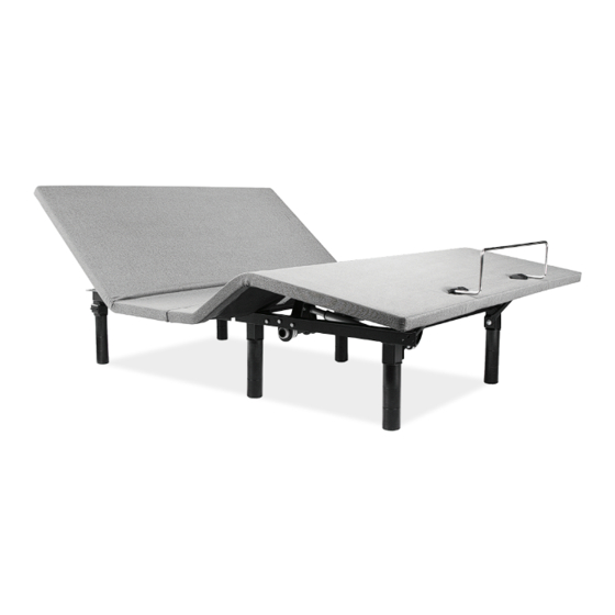
- Page 1 Vanguard OWNER’S MANUAL Actual product appearance and functionality may vary from photographs, illustrations and descriptions included in this manual.
-
Page 2: Table Of Contents
table of contents Safety Precautions and Usage Statements ............... 1-3 Parts List . -
Page 3: Safety Precautions And Usage Statements
IN-HOME USE AND HOSPITAL STANDARDS: properly, or it has been dropped into water. Only use this bed base for Enso adjustable bed bases are designed solely for in-home use. This its intended use as described in this manual. Do not use accessories/ base was not designed as a hospital bed and is not designed to meet attachments that are not recommended by the manufacturer. - Page 4 TOLERANCE of the base creating a contact noise. When entering, exiting or shifting All Enso adjustable foundations, depending on make and model, are weight on the base, this contact noise may be audible as the wheels make designed and manufactured to perform and function within designated contact.
-
Page 5: Safety Precautions And Usage Statements
safety precautions and usage statements cycle. Attempting to circumvent or exceed this rating will shorten the BREAK IN PERIOD: life expectancy of the product and may void the warranty. The massage You can speed up the break-in period by simply spending time in the motors are not designed to operate continuously for more than 30 minutes adjustable bed through activities such as reading, watching TV or playing at a time. -
Page 6: Parts List
parts list Before discarding the packing materials - ensure all the parts are accounted for. All electronics and components that need to be installed are located in boxes under the base or attached to the frame. Wired Remote Control (1) Mattress Retainer Bar (1)* Legs (6) ‡*... -
Page 7: Base And Remote Overview
base and remote overview Head Motor Lifts foot portion Lifts head portion of the base. of the base. Raise head and foot Lowers foot simultaneously. portion of the base. Lower head Lowers head and foot portion of the simultaneously. base. Foot Motor... -
Page 8: Quick Reference Guide
quick reference guide Not to scale. For illustration purposes only. Read all instructions before beginning installation. ELECTRONICS OVERVIEW Foot Motor Head Motor Power Connection Cord Wired Power Connection Remote Cord Power Cord Power Supply If installing a split unit - see page 11. -
Page 9: Installation Guide
installation guide STEP 1 STEP 4 With the help of an able-bodied assistant, place the carton on the To install the legs, thread the washer over the bolt of the leg with floor with the arrows pointing downwards. the recessed side facing the leg, and tighten by hand. Do not over tighten. - Page 10 installation guide STEP 5 STEP 8 Plug the power cord into a power source. Uncoil power connection cord from A surge protector is recommended. the head actuator and plug into Power Supply. STEP 6 STEP 9 Uncoil the Power Cord and connect to the Quickly test remote functions to verify proper setup before placing Power Supply.
-
Page 11: Connecting Strap
connecting strap (optional) If a split setup is being installed, optional plastic connecting straps can be used to help secure the bases together. To purchase optional accessories, please call 1-844-534-3676. STEP 1 STEP 2 With the bases in their desired location, slightly loosen both legs to Slide side (a) of the connecting strap onto leg bolt. -
Page 12: Syncing Two Bases
syncing two bases (optional) A Y-Cord is included with Twin Long and Split Cal King bases only (not available on Queen, Full or Full-Long size bases). The Y-Cord connects two bases to a single remote for the synchronization of two bases. STEP 1 STEP 4 Unplug bases from power source. -
Page 13: Headboard Brackets
headboard bracket installation guide (optional) Headboard Brackets are an optional accessory. A 9/16” (14 mm) & 1/2” (13 mm) socket and crescent wrench are necessary to complete installation. STEP 1 STEP 2 a.) Align the bracket and to the holes in the frame with the tabs Attach the plastic spacer and T-Bracket. -
Page 14: Troubleshooting
troubleshooting If one or more functions on the bed base have stopped operating: • Check under the bed base to verify that the wired connections are secure and that there are no cords or bedding obstructing the movement of the base. •... -
Page 15: Notes
notes... -
Page 16: Español
EN-CASA USO Y NORMAS DE HOSPITAL: Por razones de seguridad y funcionamiento óptimos, somier enchufe en un protector Enso bases ajustables de la cama están diseñados exclusivamente para su uso en el contra sobretensiones (no incluido). La base de la cama sólo debe ser conectado hogar. - Page 17 Mantener en un mínimo de 30 Todas las bases ajustables Enso, dependiendo de la marca y el modelo, están cm (12 pulgadas) de distancia de las fuentes de calor directo. Para una limpieza más diseñados y fabricados para llevar a cabo y función dentro de los parámetros de...
- Page 18 español distribución desigual de peso puede hacer que la base para elevar de manera sujeto a las dos condiciones siguientes: 1) Este dispositivo no puede causar ninguna desigual. interferencia perjudicial y 2) Este dispositivo deberá aceptar cualquier interferencia • Llame a Servicio al Cliente para cualquier problema técnico. No trate de forzar la recibida, incluso si la interferencia causara un funcionamiento indeseado.
- Page 19 español No apriete en exceso Remoto: PASO 5: Desenrosque el cable de entrada (conectado al puerto de energía de la caja de control) y conéctelo a la fuente de energía. Levanta parte de la cabeza de la cama. PASO 6: Desenrosque el cable de electricidad y conéctelo a la fuente de energía. Sube la cabeza y el pie.
-
Page 20: Español
español puerto remoto con cable en la caja de control. Repita para el otro extremo del cable y • Plug base de la cama a una toma eléctrica diferente, o toma de corriente de la segunda caja de control. prueba con otro aparato de trabajo (se recomienda un protector de sobretensión PASO 3: Conecte remoto en Y-Cord. -
Page 21: Français
MATÉRIAUX sur ou sous le lit. Les enfants ne doivent pas utiliser la base de lit sans surveillance d'un Des bases réglables Enso sont construits à partir de divers matériaux tels que le bois, adulte. les métaux, les matières plastiques et des textiles. Tension, pression ou appliquée sur le Stimulateurs cardiaques: châssis, la plate-forme ou un pont à... - Page 22 Gardez au moins 30 Toutes les bases réglables Enso, en fonction de la marque et le modèle, sont conçus cm (12 pouces), loin des sources de chaleur directe. Pour un nettoyage plus approfondi, et fabriqués pour exécuter et la fonction dans les paramètres désignés contrôle de la...
- Page 23 français Utilisez un savon doux et de l'eau pour nettoyer votre base réglable si la coloration se autorisés sur l'antenne ou le périphérique. Toute modification apportée à l'antenne ou produit. dispositif peut amener le dispositif à dépasser l'exigence d'exposition RF et est terminée Notez que les bases réglables sont recommandés pour une utilisation avec des matelas à...
- Page 24 français Levez la tête et le pied. que le bloc d'alimentation et tous les câbles liés à cette vont directement à la protection partie de pied Ascenseurs du lit. contre les surcharges souhaitée. Pg 8 -. Guide d'installation Diminue partie de pied du lit. Abaisse la tête et du pied ÉTAPE 7: tourner avec précaution la base et placez les jambes sur le sol.
-
Page 25: Français
français soire optionnel. Un connecteur 9/16 "et 1/2" clé sont nécessaires pour terminer l'installation. ÉTAPE 1: a.) Aligner le support et les trous dans le cadre avec les languettes tournées vers l'extérieur. Librement fixer le support au poste de jambe avec deux boulons, écrous et rondelles. - Page 26 Nationwide Customer Service ©2016 Ergomotion Inc V001_07/2016 Phone 1.844.534.3676 1.805.979.9399 Email info@ergomotion.com www.ergomotion.com Serial Number:...
Need help?
Do you have a question about the Vanguard and is the answer not in the manual?
Questions and answers