Table of Contents
Advertisement
Quick Links
Advertisement
Table of Contents

Subscribe to Our Youtube Channel
Related Manuals for Marshall Electronics VS-11


Summary of Contents for Marshall Electronics VS-11
- Page 1 Marshall Electronics VS‐11 HD Video Server H.264 Encoder / Decoder User Manual ...
- Page 2 Product options and specifications can be changed without notice. The information in this manual is furnished for informational use only and should not be construed as a commitment by Marshall Electronics, Inc. Marshall Electronics, Inc. assumes no responsibility or liability for any errors or inaccuracies that may appear in this publication.
-
Page 3: Table Of Contents
5.2 Video Configuration ....................56 5.3 Network Configuration ....................57 5.4 Event Configuration ....................59 5.5 Display Configuration ....................61 6 - VS Manager ........................62 7 - Appendix..........................63 User Manual VS-11 – V0.2 Page 3 of 64 2/13/12... -
Page 4: Introduction
Data Pass-Through Mode: Serial Data Communication between IP Camera and Decoder Data Pass-Through Mode: Serial Data Communication between Encoder-Decoder Sensor and Alarm Supports direct connections of External Sensor and Alarm Devices Event Alarm User Manual VS-11 – V0.2 Page 4 of 64 2/13/12... -
Page 5: Product And Accessories
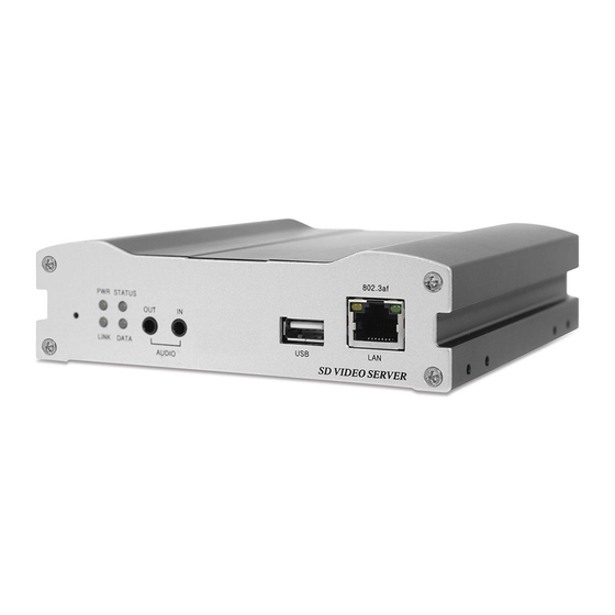
System Configuration using Internet Explorer High Reliability Reliable Embedded System System Recovery by Dual Watch-Dog Functions 1.3 Products and Accessories Video Server Power Adapter & Cable User Manual Screws Brackets Software CD User Manual VS-11 – V0.2 Page 5 of 64 2/13/12... - Page 6 USB USB Port for any USB Device LAN (Ethernet) 100/10-Base-T Ethernet Interface Reset Button Initialization of Network Setting ⑨ ④ ② ⑧ ⑦ ⑤ ③ ⑥ ① User Manual VS-11 – V0.2 Page 6 of 64 2/13/12...
- Page 7 Serial Port 2 (COM2) for PTZ Control, etc. Support RS-422 and RS-485 Protocol RS-232 (Com1) Serial Port 1 (COM1) for PTZ Control, etc. Support RS-232 Protocol VIDEO OUT Video Output VIDEO IN Video Input User Manual VS-11 – V0.2 Page 7 of 64 2/13/12...
-
Page 8: System Connections
Audio and Serial data are transferred in either direction. An Encoder and Decoder can be connected by setting the Encoder’s Address for the Decoder’s Remote IP. User Manual VS-11 – V0.2 Page 8 of 64 2/13/12... - Page 9 In this arrangement, video and audio can be re-transmitted from a center to another center. The arrangement is useful when the network bandwidth at the site is limited while there is more than one center wanting to monitor the site. User Manual VS-11 – V0.2 Page 9 of 64 2/13/12...
- Page 10 VMS (Video Management System) is a Windows based remote monitoring program to access multiple encoders for real-time monitoring or control of the encoders and connected cameras. Please refer to VMS User Manual for more information on VMS. User Manual VS-11 – V0.2 Page 10 of 64 2/13/12...
-
Page 11: Installation
Please refer to the VS Manager manual for instructions on how to find the IP address of the camera and to make necessary changes. User Manual VS-11 – V0.2 Page 11 of 64 2/13/12... - Page 12 These LED’s above show that the Decoder has started without connecting to an Encoder. Once an Encoder is connected, the color of “LINK” LED Display will turn green and the “DATA” LED will blink as video or audio data transmissions occur. User Manual VS-11 – V0.2 Page 12 of 64 2/13/12...
- Page 13 LINK Red Blinking Decoder Only: trying to connect to an Encoder Orange Illegal Connection (unsupported combination of system modes) Green Data Transmission in Progress DATA Data Loss No Data Transmission User Manual VS-11 – V0.2 Page 13 of 64 2/13/12...
-
Page 14: System Operation
If the Video Server’s IP Address is entered on Internet Explorer, the system will ask for confirmation to install Active-X Control. Once authorized, Internet Explorer will start to display video images from the Encoder as shown below: Default IP Address : http://192.168.10.100 User Manual VS-11 – V0.2 Page 14 of 64 2/13/12... - Page 15 Sensor Input Displays the status of the sensor in real time. This camera supports One Sensor Input. When the sensor of the camera is working, the sensor light turns red. User Manual VS-11 – V0.2 Page 15 of 64 2/13/12...
- Page 16 Set the number of video frames to be buffered before being displayed on web browser. Larger values result in smoother video by sacrificing the latency. A setting of 10 ~ 15 frames can be generally used for most situations. User Manual VS-11 – V0.2 Page 16 of 64 2/13/12...
-
Page 17: Initialization Of Ip Address
3. Once the system reboots, IP Address will be set to the System Default as below: IP Mode IP Address Fixed IP 192.168.10.100 Subnet Mask Gateway 255.255.255.0 192.168.10.1 Base Port HTTP Port 2222 User Manual VS-11 – V0.2 Page 17 of 64 2/13/12... - Page 18 The configurations are grouped into 10 categories: System, Video, Audio, Network, Serial, Event, PTZ, Record, User and Camera. Any configuration changes are not applied until “Apply” Button is pressed. Leaving the page without pressing “Apply” will discard any changes made. User Manual VS-11 – V0.2 Page 18 of 64 2/13/12...
-
Page 19: Remote Configuration
4- Remote Configuration ___________________________________________________________________________ 4.1 System Configuration User Manual VS-11 – V0.2 Page 19 of 64 2/13/12... - Page 20 4. The camera will reboot automatically after completing the upgrade. Do not turn off the camera during upgrading. Config Backup & Restore Backup All the settings of the configuration can be saved and stored. User Manual VS-11 – V0.2 Page 20 of 64 2/13/12...
- Page 21 Factory Reset All Settings including user accounts and logs are cleared. Factory Reset except Network Settings All the Settings except for Current Network Settings are changed to Default Values. User Manual VS-11 – V0.2 Page 21 of 64 2/13/12...
-
Page 22: Video Configuration
4- Remote Configuration ___________________________________________________________________________ 4.2 Video Configuration User Manual VS-11 – V0.2 Page 22 of 64 2/13/12... - Page 23 Input Video. Quality Mode is preferred when Constant Video Quality is required and Network Bandwidth is sufficient for streaming of a highly varying Bit Rate. User Manual VS-11 – V0.2 Page 23 of 64 2/13/12...
- Page 24 Mode or Quality Mode can be selected for the Preference Mode. MJPEG supports Quality Mode only. Motion Detection Use Motion Detection Determine if the Motion Detection function will be used. User Manual VS-11 – V0.2 Page 24 of 64 2/13/12...
- Page 25 System ID and/or Server Time can be displayed over the video window in the Internet Explorer Browser. Items can be turned on or off individually and the position also can be configured. This information will be displayed after the video is decompressed. User Manual VS-11 – V0.2 Page 25 of 64 2/13/12...
- Page 26 Controls input video contrast by selecting values between 0 and 100. Hue Controls input video Hue by selecting values between 0 and 100. Saturation Controls input video saturation by selecting values between 0 and 100. User Manual VS-11 – V0.2 Page 26 of 64 2/13/12...
- Page 27 Output Format Output Format Menu appears only when Enable Preview is ON. Select the output format for the monitor preview according to the video output and monitor specification. User Manual VS-11 – V0.2 Page 27 of 64 2/13/12...
-
Page 28: Audio Configuration
Camera is connected to a Decoder, the Decoder’s Audio Algorithm should be set identically to transmit audio properly. Mode Select Audio Operation Mode: Mode Action No Operation Tx-Only Transmit Only Rx-Only Receive Only Tx & Rx Transmit and Receive User Manual VS-11 – V0.2 Page 28 of 64 2/13/12... - Page 29 Configure the Audio Source to be played on Audio Output Port. Decoded Audio: Audio Stream from client is played. Loopback: Audio Data from the Audio Input Port is looped back to the Audio Output Port. User Manual VS-11 – V0.2 Page 29 of 64 2/13/12...
-
Page 30: Network Configuration
4- Remote Configuration ___________________________________________________________________________ 4.4 Network Configuration User Manual VS-11 – V0.2 Page 30 of 64 2/13/12... - Page 31 DNS queries. That server, called a name server, will hold a list of all the IP addresses within its network, plus a cache of IP addresses for recently accessed computers outside the network. User Manual VS-11 – V0.2 Page 31 of 64 2/13/12...
- Page 32 When Zeroconf is ON, it allows the discovery by the client according to Zeroconf protocol. WS Discovery Discovery function based on Web Service is enabled. It allows the discovery by Client SW which is supporting Onvif. User Manual VS-11 – V0.2 Page 32 of 64 2/13/12...
- Page 33 User Name: Enter the User Name that will be used in the SDP File. File Name: Enter the File Name that will be used for the SDP File Name. This can be accessed through http://ServerAddress/filename User Manual VS-11 – V0.2 Page 33 of 64 2/13/12...
- Page 34 For Example: A router could send a message if one of its redundant power supplies fails or a printer could send an SNMP trap when it is out of paper. User Manual VS-11 – V0.2 Page 34 of 64...
- Page 35 In Fixed IP Mode, the set IP will be registered on the DDNS server. In DHCP Mode, dynamically assigned IP will be registered on the DDNS server. Check IP Disable should be unchecked to obtain Public IP in the Network. User Manual VS-11 – V0.2 Page 35 of 64 2/13/12...
- Page 36 MAC Address: The MAC Address is used for the Camera’s DDNS Registration and is displayed on the DDNS Server. Connecting: Client IP Addresses that are currently connected to system are listed. User Manual VS-11 – V0.2 Page 36 of 64 2/13/12...
-
Page 37: Serial Configuration
4- Remote Configuration ___________________________________________________________________________ 4.5 Serial Configuration User Manual VS-11 – V0.2 Page 37 of 64 2/13/12... - Page 38 NO (Normally Open) when closed. port normally closed NC (Normally Closed) activated when opened. The function of the sensor port is set based on the type of the sensor connected. User Manual VS-11 – V0.2 Page 38 of 64 2/13/12...
- Page 39 Click desired “Cell” to set schedule. Click desired “Time Line” or “Date Line” to set schedule. To set cells in the schedule, click on “Empty Cells” below. User Manual VS-11 – V0.2 Page 39 of 64 2/13/12...
-
Page 40: Event Configuration
4- Remote Configuration ___________________________________________________________________________ 4.6 Event Configuration User Manual VS-11 – V0.2 Page 40 of 64 2/13/12... - Page 41 Alarm Duration and Beep Activation Set the duration of alarm or beep activation for each event. If it is set to continuous, it will be active until it is manually reset. User Manual VS-11 – V0.2 Page 41 of 64 2/13/12...
- Page 42 Email Test: Email sending can be tested with this button. The configured settings should be saved first by pressing the “Apply” button before using the Email Test function. One of the following messages will be sent as a result of the test: User Manual VS-11 – V0.2 Page 42 of 64 2/13/12...
- Page 43 %ADDR: server address (Domain Name when DDNS is used; otherwise IP Address) “.avi” or “.jpg” will be automatically added at the end of filenames depending on the type of video file. User Manual VS-11 – V0.2 Page 43 of 64 2/13/12...
- Page 44 FTP server can be full. Failed to delete the test file. The user of the ID Failed to Erase File doesn’t have the privilege for file deletion. User Manual VS-11 – V0.2 Page 44 of 64 2/13/12...
-
Page 45: Preset Configuration
4- Remote Configuration ___________________________________________________________________________ 4.7 Preset Configuration Preset Select preset # and insert the name of preset. Set camera position for the preset and press Save List button. User Manual VS-11 – V0.2 Page 45 of 64 2/13/12... -
Page 46: Record Configuration
4- Remote Configuration ___________________________________________________________________________ 4.8 Record Configuration User Manual VS-11 – V0.2 Page 46 of 64 2/13/12... - Page 47 Be sure to restart the system after connecting an SD card. During booting, the system reads status of disk and initializes it. Once the initialization of a disk is finished, the status of disk is shown on Record Page of Web-Based Setup. User Manual VS-11 – V0.2 Page 47 of 64 2/13/12...
- Page 48 In this mode, FTP upload by event is automatically disabled. Select Video Select video stream to record. Manual Record When “ON” is selected, record is operated regardless of schedule. User Manual VS-11 – V0.2 Page 48 of 64 2/13/12...
- Page 49 Pre-Event Time Specify the duration of recording before an event happens. Post-Event Time Specify the duration after the event is cleared. User Manual VS-11 – V0.2 Page 49 of 64 2/13/12...
- Page 50 2. First, choose the date for search and the list of AVI files will be shown. 3. The file name shows the date and time: “Date Begin Time End Time.avi” User Manual VS-11 – V0.2 Page 50 of 64 2/13/12...
- Page 51 1. Selecting an AVI file will show a dialog for opening or saving the file 2. Pressing Save button, the file will be stored in the PC. The AVI file can be played with Windows Media Player. User Manual VS-11 – V0.2 Page 51 of 64 2/13/12...
- Page 52 1. If you want to delete recorded files, select the files by checking the item in front of each file and press Delete button. 2. It is possible to delete multiple files at once. User Manual VS-11 – V0.2 Page 52 of 64 2/13/12...
-
Page 53: User Configuration
User control Guest Live viewing only Add User Press Add button. The following window will appear: Enter User ID and password (Up to 15 characters) and select Privilege Level User Manual VS-11 – V0.2 Page 53 of 64 2/13/12... - Page 54 When Skip Login is set to Enable, the login step is skipped. The privilege level after login in is determined by the setting of Privilege Level After Login Skipped. User Manual VS-11 – V0.2 Page 54 of 64 2/13/12...
-
Page 55: Decoder Configuration
5- Decoder Configuration ___________________________________________________________________________ Decoder Configuration is slightly different from Encoder Configuration. Different configurations for the encoder will be explained in Decoder Configuration. 5.1 System Configuration User Manual VS-11 – V0.2 Page 55 of 64 2/13/12... -
Page 56: Video Configuration
You can store maximum 30 decoded frames temporarily by using buffering before displaying the frames. Displaying stored frames is smoother than displaying in real time. However, displaying stored frames causes delay because of process of buffering. User Manual VS-11 – V0.2 Page 56 of 64 2/13/12... -
Page 57: Network Configuration
5- Decoder Configuration ___________________________________________________________________________ 5.3 Network Configuration Network page of Decoder has a section for specifying the remote system to connect and the other functions are same as Network Configuration of Encoder. User Manual VS-11 – V0.2 Page 57 of 64 2/13/12... - Page 58 SS IP Address: IP address of Streaming Server. SS Port: Enter Port number that is set when registering Streaming Server. SS ID: Enter Streaming Server ID. SS Password: Enter Streaming Server Password. User Manual VS-11 – V0.2 Page 58 of 64 2/13/12...
-
Page 59: Event Configuration
Alarm1/Alarm2 Triggers alarm (relay) port. Sends Email to the specified address. Email AVI file can be attached Upload AVI file to a specified FTP server Moves the PTZ to associated preset Preset position User Manual VS-11 – V0.2 Page 59 of 64 2/13/12... - Page 60 Set the duration of alarm or beep activation in case of an event. If it is set to continuous, it will be in active state until an operator reset it manually. User Manual VS-11 – V0.2 Page 60 of 64...
-
Page 61: Display Configuration
Select from Video, Audio and Serial to be indicated by Data LED. When there is the selected Data (Video or Audio or Serial) Communication between the Encoder and the Decoder, Data LED will indicate the status. User Manual VS-11 – V0.2 Page 61 of 64 2/13/12... -
Page 62: Vs Manager
Finding Servers on the LAN and assigning IP Addresses. Monitoring Server Status: Encoding/Decoding, Serial, Sensor, etc. Diagnostic Function: PING, Network Bandwidth Measurement, Video/Audio Output, Port Check, Serial Port Check. Firmware Upgrade. User Manual VS-11 – V0.2 Page 62 of 64 2/13/12... -
Page 63: Appendix
Relay Type Contact Rating : 1A 30VDC Switching Power : Max 30W 62.5VA Switching Voltage : Max 60VDC Alarm Signal Output Type NO/NC Contact Signals Connection to External Device User Manual VS-11 – V0.2 Page 63 of 64 2/13/12... - Page 64 It is selectable by S/W Setup Marshall Electronics, Inc. 1910 East Maple Ave. El Segundo, CA 90245 Tel: (800) 800-6608 / (310) 333-0606 Fax (310) 333-0688 www.LCDRacks.com sales@lcdracks.com User Manual VS-11 – V0.2 Page 64 of 64 2/13/12...
Need help?
Do you have a question about the VS-11 and is the answer not in the manual?
Questions and answers