D-Link DGS-1216T User Manual
16-port 10/100/1000mbps + 2 combo mini gbic gigabit smart switch
Hide thumbs
Also See for DGS-1216T:
- Manual (61 pages) ,
- Product manual (52 pages) ,
- Getting started manual (43 pages)

Related Manuals for D-Link DGS-1216T


Summary of Contents for D-Link DGS-1216T
- Page 1 D-Link DGS-1216T 16-Port 10/100/1000Mbps + 2 Combo Mini GBIC Gigabit Smart Switch Manual Building Networks for People...
-
Page 2: Table Of Contents
Understanding LED Indicators ...15 Power and System LEDs ...15 Ports 1~16 Status LEDs...15 Option Ports mini-GBIC 15 & mini-GBIC 16 mini-GBIC Status LEDs...16 Configuration...17 Installing the Web Management Utility...17 Discovery List...18 Monitor List...18 Device Setting...20 Toolbar ...22 Configuring the Switch...23... - Page 3 Setup Menu...25 Configuring Setup Setting ...25 Port Settings...25 VLAN Settings (Virtual Local Area Network)...27 Trunk Setting ...28 Mirror Setting ...29 Device Status ...29 Statistic ...29 System Setting ...30 Trap Setting ...31 Set Password...32 Backup Setting...32 Reset Setting ...33 Logout...33 Technical Specifications...37...
-
Page 4: About This Guide
Ethernet, 100Mbps Fast Ethernet, and 10Mbps Ethernet network capabilities in a highly flexible package. Purpose This manual discusses how to install and configure the DGS-1216T Web Smart Switch. Terms/Usage In this manual, the term “Switch” (first letter upper case) refers to your DGS- 1216T Web Smart Switch, and “switch”... -
Page 5: Introduction
INTRODUCTION This chapter describes the features of the DGS-1216T and some background information about Ethernet/Fast Ethernet/Gigabit Ethernet switching technology. Gigabit Ethernet Technology Gigabit Ethernet is an extension of IEEE 802.3 Ethernet utilizing the same packet structure, format, and support for CSMA/CD protocol, full-duplex, flow... -
Page 6: Fast Ethernet Technology
Ethernet or Fast Ethernet LAN segments. Switching is a cost-effective way of increasing the total network capacity available to users on a local area network. A switch increases capacity and decreases network loading by dividing a local area network into different segments, which do not compete with each other for network transmission capacity. -
Page 7: Vlan (Virtual Local Area Network)
Cost Reduction: VLANs can be used to create multiple broadcast domains, thus eliminating the need of expensive routers. Port-based (or port-group) VLAN is the common method of implementing a VLAN, and is the one supplied in the Switch. Features 16×10/100/1000Mbps Auto-negotiation Gigabit Ethernet ports... - Page 8 Supports port-base QoS Supports Port-trunking Supports Port-mirroring Supports Port-setting for Speed/Disable, Flow control Easy configuration via Web Browser Easy setting via Web Management Utility Standard 19” Rack-mount size...
-
Page 9: Unpacking And Installation
This chapter provides unpacking and installation information for the Switch. Unpacking Open the shipping carton of the Switch and carefully unpacks its contents. The carton should contain the following items: One DGS-1216T Web Smart Switch One AC power cord, suitable for your area’s electrical power... -
Page 10: Rack Mounting
Figure 1. Attach the adhesive rubber pads to the bottom. Rack Mounting The Switch can be mounted in an EIA standard-size, 19-inch rack, which can be placed in a wiring closet with other equipment. Attach the mounting brackets at the Switch’s front panel (one on each side), and secure them with the provided screws. -
Page 11: Connecting Network Cable
AC Power The Switch uses a 100-240V AC, 50-60 Hz AC power supply. The power switch is located at the rear of the unit adjacent to the AC power connector and the system fan. The Switch’s power supply will adjust to the local power source automatically and may be turned on without having any or all LAN segment cables connected. -
Page 12: Identifying External Components
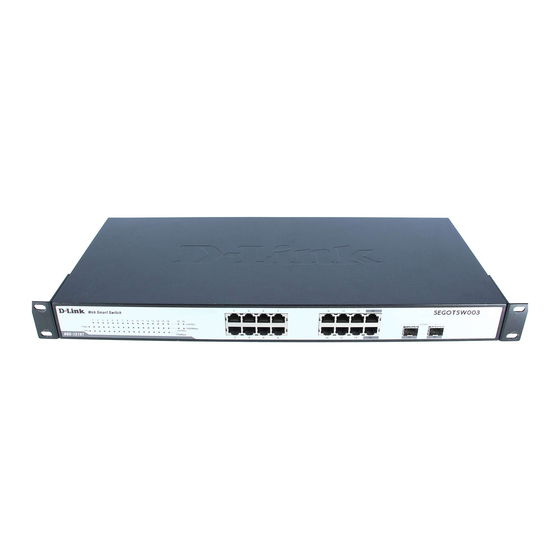
This chapter describes the front panel, rear panel, and LED indicators of the Switch. Front Panel The figure below shows the front panels of the Switch. Figure 4. Front panel of 16-port Gigabit Ethernet Switch. LED Indicator: Comprehensive LED indicators display the status of the Switch and the network (see the LED Indicators chapter below). -
Page 13: Rear Panel
Rear Panel ● Rese Figure 5. Rear panel of the Switch. AC Power Connector: This is a three-pronged connector that supports the power cord. Plug in the female connector of the provided power cord into this connector, and the male into a power outlet. Supported input voltages range from 100-240V AC at 50-60Hz. -
Page 14: Understanding Led Indicators
Figure 6. LED indicators of the Switch. Power and System LEDs Power: Power Indicator : When the Power LED lights on, the Switch is receiving power. : When the Power turns off or the power cord is not properly connected. CPU: Management Indicator Blinking : When the CPU is working, the System LED is blinking. -
Page 15: Option Ports Mini-Gbic 15 & Mini-Gbic 16 Mini-Gbic Status Leds
When the 1000Mbps LED lights on, the respective port is connected to a 1000Mbps Gigabit Ethernet network. When the respective port is connected to a 10Mbps Ethernet or 100Mbps Fast Ethernet network. 100Mbps When the 100Mbps LED lights on, the respective port is connected to a 100Mbps Fast Ethernet network. -
Page 16: Configuration
CONFIGURATION Through the Web browser you can configure settings on the Switch such as VLAN, Trunking, QoS… etc. With the included Web Management Utility, you can easily discover all the Web Managed switches, assign IP Addresses, change passwords and upgrade new firmware. -
Page 17: Discovery List
The Web Management Utility is divided into four parts: Discovery List, Monitor List, Device Setting, and Toolbar function. For detailed explanation, follow the section below. Discovery List This is the list where you can discover all the Web management devices in the entire network. By clicking the “Discovery”... - Page 18 Gateway: Shows the Gateway set of the device. View Trap: The Trap function can receive the events that occur from the Web Management Switch in the Monitor List. There is a light indicator behind the “View Trap” button. When the indicator lights green, it means that there is no trap transmitted.
-
Page 19: Device Setting
Figure 9. Note: In order to receive Trap information, the Switch has to be configured with Trap IP and Trap Events in Web browser, which are available in the Trap Setting Menu (see Page 45 for detail). Add Item: To add a device to the Monitor List manually, enter the IP Address of the device that you want to monitor. - Page 20 Figure 10. Configuration Setting Password Change: To change the password, enter the original password, the new password, and confirm the original password. Click the “Set” button to proceed with the password change. Figure 11. Password Change Firmware Upgrade: When the device has a new function, there will be a new firmware to update the device.
-
Page 21: Toolbar
Web Access: Double click the device in the Monitor List or select a device in the Monitor List and click the “Web Access” button to access the device in the Web browser. Toolbar The toolbar in the Web Management Utility has four main tabs: File, View, Options, and Help. -
Page 22: Configuring The Switch
The “Help TAB” has the About function. It will show the current version of the Web Management Utility. Configuring the Switch The DGS-1216T Web Smart Switch has a Web GUI interface for smart switch configuration. The Switch can be configured through the Web Browser. A network administrator can manage, control, and monitor the Switch from the local area network. - Page 23 Through the Web Management Utility, you do not need to remember the IP Address. Select the device shown in the Monitor List of the Web Management Utility to settle the device on the Web Browser. When the following dialog page appears, enter the default password "admin"...
-
Page 24: Setup Menu
Setup Menu When the main page appears, find the Setup menu in the left side of the screen (Figure 16). Click on the setup item that you want to configure. There are eleven options: Port Settings, VLAN Settings, Trunk Setting, Mirror Setting, Device Status, Statistic, System Settings, Trap Setting, Password Setting, Backup Setting, and Reset Setting, as shown in the Main Menu screen. - Page 25 The Link Status in the screen will show the connection speed and duplex mode. If the port is disconnected, the dialog box will display down. Figure 17. Port Setting Note: Be sure that you reset the Gigabit port when transferring the media type (Fiber to Copper or Copper to Fiber).
-
Page 26: Vlan Settings (Virtual Local Area Network)
10M Half, Auto, and Disable) for speed or port disable selections. Flow Control: This setting determines whether or not the Switch will be handling flow control. Set FlowCtrl to Enable to avoid data transfer overflows. If set to Disable, there is either no flow control or other hardware/software management. -
Page 27: Trunk Setting
the “Add Group” button. The new VLAN configuration window will appear. You can fill in the description in order to describe this VLAN Group and check on the port to be a member of this VLAN Group. Click the “Apply” button to execute the setting. Figure 19. -
Page 28: Mirror Setting
Port Mirroring is a method of monitoring network traffic that forwards a copy of each incoming and/or outgoing packet from one port of a network switch to another port where the packet can be studied. It enables the manager to keep close track of switch performance and alter it if necessary. -
Page 29: System Setting
Figure 23. Statistic For detailed packet information, click on the ID parameter as shown in Figure 24. Figure 24. System Setting The System Setting includes the System name, Location name, Login Timeout, IP Address, Subnet Mask, and Gateway. Through the Web Management Utility, you can easily recognize the device by using the System Name and the Location Name. -
Page 30: Trap Setting
Figure 25. Trap Setting The Trap Setting enables the device to monitor the Trap through the Web Management Utility. Set the Trap IP Address of the manager where the trap will be sent. Figure 26. Trap Setting System Events: Monitoring the system’s trap. Device Bootup: A trap when booting up the system. -
Page 31: Set Password
If you forget the password, press the “Reset” button in the rear panel of the Switch. Current switch settings, such as VLAN, Port Setting… etc. will be lost and the Switch will be restored to the factory default settings. Figure 27. Set Password Backup Setting The backup tools help you to backup the current switch settings. -
Page 32: Reset Setting
Figure 28. Backup Setting Note: When restoring a recorded file, the current password will not be erased. Reset Setting The Factory Reset button helps you to reset the device back to the factory default settings. Be aware that the entire configuration will be reset. -
Page 33: Physical And Environmental
General Standards IEEE 802.3 10BASE-T Ethernet IEEE 802.3u 100BASE-TX Fast Ethernet IEEE 802.3ab 1000BASE-T Gigabit Ethernet IEEE 802.3x Full Duplex Flow Control IEEE 802.3z 1000BASE-SX/LX Gigabit Ethernet Protocol CSMA/CD Data Transfer Ethernet: 10Mbps (half-duplex), 20Mbps (full-duplex) Rate Fast Ethernet: 100Mbps (half-duplex), 200Mbps (full-duplex) Gigabit Ethernet: 2000Mbps (full-duplex) Topology Star... - Page 34 Transmits Method: Store-and-forward Filtering Address 4K entries per device Table: Packet 10Mbps Ethernet: 14,880/pps Filtering/Forwarding 100Mbps Fast Ethernet: 148,800/pps Rate: 1000Mbps Gigabit Ethernet: 1,488,000/pps MAC Address Automatic update Learning: Transmits Method: Store-and-forward RAM Buffer: 272K bytes per device...
-
Page 35: Warranty Information
D-Link’s sole obligation shall be to repair or replace the defective Hardware during the Warranty Period at no charge to the original owner or to refund at D-Link’s sole discretion. Such repair or replacement will be rendered by D-Link at an Authorized D-Link Service Office. - Page 36 D-Link Systems, 17595 Mt. Herrman Street, Fountain Valley, CA. 92708. D- Link will not be held responsible for any packages that are lost in transit to D-Link. The repaired or replaced packages will be shipped to the customer via UPS Ground or any common carrier selected by D-Link, with shipping charges prepaid.
- Page 37 D-Link; Products that have been purchased from inventory clearance or liquidation sales or other sales in which D-Link, the sellers, or the liquidators expressly disclaim their warranty obligation pertaining to the product. Repair by anyone other than D-Link or an Authorized D-Link Service Office will void this Warranty.
- Page 38 D-Link Corporation/D- Link Systems, Inc., as stipulated by the United States Copyright Act of 1976. Contents are subject to change without prior notice.
- Page 39 Product registration is entirely voluntary and failure to complete or return this form will not diminish your warranty rights.
Need help?
Do you have a question about the DGS-1216T and is the answer not in the manual?
Questions and answers