Table of Contents
Advertisement
Advertisement
Table of Contents

Related Manuals for Honda FF500


Summary of Contents for Honda FF500
- Page 2 ‘‘e-SPEC’’ was originally created with our wish to ‘‘preserve nature for generations to come’’. Now it also symbolizes environmentally responsible technologies applied to Honda engines, power equipment, outboard engines, etc., and is to be used to identify those products which adopt the highest levels...
- Page 3 All information in this publication is based on the latest product information available at the time of printing. Honda Motor Co., Ltd. reserves the right to make changes at any time without notice and without incurring any obligation. No part of this publication may be reproduced without written permission.
-
Page 4: Table Of Contents
..............32 8. MAINTENANCE ................34 9. CLEANING AFTER USE ..............53 10. TRANSPORTING/STORAGE ............54 11. TROUBLESHOOTING ..............57 12. SPECIFICATIONS ................60 13. MAJOR Honda DISTRIBUTOR ADDRESSES IN EUROPE ... . 61... -
Page 5: Safety Instructions
To ensure safe operation For your safety and the safety of others, pay special attention to these precautions: Honda tiller is designed to give safe and dependable service if operated according to instructions. Read and understand the Owner’s Manual before operat- ing the tiller. - Page 6 − To ensure safe operation Operator responsibility Read the owner’s manual carefully. Be familiar with the controls and their proper use of the tiller. Use the tiller for the purpose it is intended that is, cultivating the soil. Any other use could be dangerous or damage the equipment, especially never use it to cultivate soil containing rocks, stones, wires and any other hard materials.
- Page 7 − To ensure safe operation Operator responsibility Stop the engine in the following cases: Whenever you leave the tiller unattended. − Before refueling − When stopping the engine, move the throttle lever to the LOW position, then turn the engine switch OFF. If the fuel valve is equipped on the tiller, be sure to turn the fuel valve OFF.
- Page 8 − To ensure safe operation Fire and burn hazard Gasoline is extremely flammable, and gasoline vapor can explode. Use extreme care when handling gasoline. Keep gasoline out of reach of children. Add fuel before starting the engine. Never remove the cap of the fuel tank or add gasoline while the engine is running or when the engine is hot.
- Page 9 − To ensure safe operation Carbon monoxide poisoning hazard Exhaust contains poisonous carbon monoxide, a colorless and odorless gas. Breathing exhaust can cause loss of consciousness and may lead to death. If you run the engine in an area that is confined or even partially enclosed, the air you breathe could contain a dangerous amount of exhaust gas.
-
Page 10: Safety Label Locations
These labels warn you of potential hazards that can cause serious injury. Read the labels and safety notes and precautions described in this manual carefully. If a label comes off or becomes hard to read, contact your Honda dealer for a replacement. EXHAUST CAUTION CUTTING DANGER READ OWNER’S MANUAL... -
Page 11: Ce Mark And Noise Label Locations
CE mark and noise label locations NOISE LABEL CE MARK Manufacturer and address Description code Year of manufacture Frame serial number Machine mass (Standard specification) Net power... -
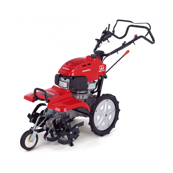
Page 12: Component Identification
COMPONENT IDENTIFICATION DIFFERENTIAL LOCK LEVER THROTTLE LEVER ENGINE COVER SPARK PLUG CAP GEARSHIFT LEVER CARBURETOR DRAIN SCREW FUEL VALVE REAR WHEEL AIR CLEANER ROTARY FRONT WHEEL... - Page 13 MAIN CLUTCH LEVER FUEL FILLER CAP ENGINE SWITCH ENGINE OIL FILLER CAP/DIPSTICK MUFFLER CHOKE KNOB HANDLEBAR RECOIL STARTER GRIP ENGINE OIL DRAIN BOLT TRANSMISSION OIL FILLER CAP CLUTCH OIL LEVEL CHECK BOLT...
-
Page 14: Pre-Operation Check
Start the engine. Is there any abnormal sound from the engine?(See pages through for starting procedure.) Does the engine stop securely by operating the engine switch?(See pages for stopping procedure.) If you notice any other abnormal symptoms, consult with your authorized Honda dealer promptly. - Page 15 Engine oil Running the engine with insufficient oil can cause serious engine damage. Stop the engine and place the tiller on the level ground with rear wheels and tines. Place a 60 mm (2.4 in) thick block under the rear wheels as shown. 60 mm Remove the oil filler cap/dipstick and TINE...
- Page 16 Air cleaner Never run the engine without the air cleaner. Rapid engine wear will result. Push the latch tabs and pull the air cleaner cover out of the air cleaner case, then disengage the lower locking tabs from the air cleaner case and remove the air cleaner cover.
- Page 17 Fuel Stop the engine and place the tiller on the level ground with rear wheels and tines. Check the fuel level, and refill the tank if the fuel level is low. Use automotive unleaded gasoline with a Research Octane Number of 91 or higher (a Pump Octane Number of 86 or higher).
- Page 18 Gasolines containing alcohol If you decide to use a gasoline containing alcohol (gasohol), be sure it’s octane rating is at least as high as that recommended by Honda. There are two types of ‘‘gasohol’’: one containing ethanol, and the other containing methanol.
- Page 19 Tools and Attachments To install a tool or attachment on the tiller, follow the instructions furnished with the tool or attachment. Ask your Honda dealer for advice if you encouter any problem or difficulty in installing a tool or attachment.
- Page 20 Tightening points Carry out the check with the tiller on a level ground and the engine stopped. Wear thick gloves when checking or tightening the rotary part. Check for looseness in fastened parts. Securely tighten all loose parts. Check for worn, bent or other damaged rotary tines. Parts to be tightened Handlebar setting bolt Tine plate and rotary part...
-
Page 21: Starting The Engine
STARTING THE ENGINE Turn the fuel valve to the ON position. Before turning the fuel valve, make sure that the drain screw is tightened securely. FUEL VALVE DRAIN SCREW Make sure the main clutch lever is in the DISENGAGED position. MAIN CLUTCH LEVER DISENGAGED Make sure the gearshift lever is in the NEUTRAL position. - Page 22 In cold weather and when the engine is cold, pull the choke knob to the CLOSE position. Do not use the choke if the engine is warm or the air temperature is high. CHOKE KNOB CLOSE CLOSE Turn the engine switch to the ON position. ENGINE SWITCH △...
- Page 23 Pull the starter grip lightly until resistance is felt, then return the starter grip once. Direction to pull Hold the handlebar with your left hand and pull the starter grip briskly in the direction of the arrow as shown. STARTER Do not allow the starter grip GRIP to snap back.
-
Page 24: High Altitude Operation
High altitude performance can be improved by specific modification to the carburetor. If you always operate the tiller at altitude higher than 1,500 m (5,000 feet) above sea level, have your authorized Honda dealer perform these carburetor modifications. Even with suitable carburetor jetting, engine horsepower will decrease approximately 3.5 % for each 300 m (1,000 foot) increase in altitude. -
Page 25: Tiller Operation
TILLER OPERATION Front wheel position adjustment Front wheel height can be changed to adjust the tilling depth and to transport the tiller. Set the tiller on a firm level ground and hold it securely by placing a suitable block under the transmission case. Pull the front wheel beam forward to move the pin out of the groove and set it in the groove you want. - Page 26 Tilling width adjustment The tilling width is factory-set at the wide position. Remove the outer rotary to narrow the tilling width. Equalize the space difference between the tilling width and the rear wheel tread. Also equalize the space in the right and left sides. As the reverse-spinning outer rotary is removed to narrow the tilling width, the tilling is only in the normal direction of rotation.
- Page 27 Rear wheel tread adjustment Rear wheel position can be changed to adjust the rear wheel tread in accordance with the tilling width. Set the tiller on a firm level ground and hold it securely by placing a suitable block under the transmission case and raising the rear wheels off the ground.
- Page 28 Handlebar position adjustment Handlebar height can be set in either the HIGH or LOW position in accordance with the work or the height of the operator. Place the tiller on a level surface with the rear wheels and tines on the ground and secure it not to move.
- Page 29 Gear selection Return the throttle lever to the low speed position and disengage the clutch before moving the gearshift lever. Avoid using excessive force on the gearshift lever. Select a gear position in accordance with the contents of the Gear Selection Table (page Always operate the gearshift lever after the main clutch has been disengaged.
- Page 30 Gear Selection Table (When engine speed is 3,000 rpm) * Gear position Tiller speed Rotary speed Suitable work 0.18 m/s Moving tiller, loading tiller onto a (0.59 ft/s) truck, taking tiller on or off field 0.31 m/s Moving tiller, loading tiller onto a (1.02 ft/s) truck, taking tiller on or off field 1.00 m/s...
- Page 31 Main clutch operation The clutch engages and disengages the power from the engine to the transmission. When operating the tiller, always walk behind and in the center of the tiller and hold the handlebar with both hands. If the tiller becomes imbalanced, an unforeseen accident may occur.
- Page 32 Squeeze the main clutch lever with care not to pinch your hand between the handlebar and main clutch lever. When the main clutch lever is released, MAIN CLUTCH LEVER the clutch is disengaged and power is not transmitted to the transmission. DISENGAGED Operate the main clutch lever smoothly.
- Page 33 Differential lock operation For normal operation set the differential lock lever in the UNLOCK position. This improves tiller’s turning ability. UNLOCK LOCK LOCK UNLOCK DIFFERENTIAL LOCK LEVER When the ground is soft and one wheel tends to slip or when only one side is to be tilled, set the differential lock in the LOCK position.
-
Page 34: Stopping The Engine
STOPPING THE ENGINE In an emergency: Turn the engine switch to the OFF position. ENGINE SWITCH In normal use: Release the main clutch lever to the DISENGAGED position. MAIN CLUTCH LEVER DISENGAGED Move the throttle lever toward the slowest position and reduce the engine speed. - Page 35 Set the gearshift lever in the NEUTRAL position. NEUTRAL GEARSHIFT LEVER NEUTRAL Turn the engine switch to the OFF position. ENGINE SWITCH Turn the fuel valve to the OFF position. FUEL VALVE...
-
Page 36: Maintenance
To prevent an accidental start-up, disconnect the spark plug cap. Use only genuine Honda parts or their equivalent for maintenance or repair. Replacement parts which are not of equivalent quality may damage the tiller. - Page 37 Perform at every indicated month or operating hour interval, whichever comes first. Service of these items requires you to have the adequate tools and skill. Consult with your authorized Honda dealer for service. Replace the engine oil every 100 operating hours when used under high load and high temperature.
- Page 38 Engine oil change Remove the oil filler cap/dipstick and the oil drain plug to drain the engine oil. Reinstall the oil drain plug and tighten it securely. Refill with the recommended oil and check the oil level (see page Reinstall the oil filler/cap dipstick Oil capacity: 0.55 (0.58 US qt , 0.48 Imp qt) OIL FILLER...
- Page 39 Air cleaner service A dirty air cleaner will restrict air flow to the carburetor. To prevent carburetor malfunction, service the air cleaner regularly. Service more frequently when operating the engine in extremely dusty areas. Never run the engine without the air cleaner. Rapid engine wear will result.
- Page 40 Tap the element lightly several times on a hard surface to remove excess dirt, or blow compressed air through the filter from the inside out. Never try to brush the dirt off; brushing will force dirt into the fibers. Replace the element if it is excessively dirty. ELEMENT Install the element and the air cleaner cover.
- Page 41 Add the recommended oil if the level is low. Recommended oil: Use SAE 0W-20 Honda 4-stroke oil or SAE 0W-20 4-stroke motor oil that meets the requirements for API service classification SL or equivalent. Always check the API service label on the oil container to be sure it includes the letters SL or equivalent.
- Page 42 Transmission oil inspection Stop the engine and set the tiller on a firm level ground with the rear wheels and tines as shown. Remove the oil filler cap and check that the oil is level with the lower edge of the oil filler hole. TINE REAR WHEEL OIL FILLER CAP...
- Page 43 Spark plug service Recommended spark plug: BPR6ES (NGK) Never use a spark plug with an improper heat range. To ensure proper engine operation, the spark plug must be properly gapped and free of deposits. Disconnect the spark plug cap. Remove the spark plug with spark plug wrench. If the engine has been running, the muffler will be very hot.
- Page 44 Check that the spark plug washer is in good condition and thread the spark plug in by hand to prevent cross-threading. After the spark plug is seated, tighten with a spark plug wrench to compress the washer. When installing a new spark plug, tighten 1/2 turn after the spark plug seats to compress the washer.
- Page 45 Throttle cable adjustment Move the throttle lever to the slowest position. THROTTLE Check the free play of the LEVER throttle lever at the end of the lever. Free play should be: − − 10 15 mm (0.4 0.6 in) If adjust is necessary, loosen the lock nut and turn the adjuster until the correct throttle lever free play is...
- Page 46 Main clutch cable adjustment Pull the main clutch lever to the ENGAGED position, and check the extension value of the clutch spring at the end of the longer spring hook as shown. Extension value should be: − − 2.5 3.5 mm (0.10 0.14 in) CLUTCH SPRING 2.5 3.5 mm −...
- Page 47 Differential lock cable adjustment Set the differential lock lever in the UNLOCK position. Check the differential lock lever free play at the end of the lever. Differential lock lever free play should be: − − 1 5 mm (0.04 0.20 in) FREE PLAY −...
- Page 48 Rotary tines inspection and replacement Wear heavy gloves to protect your hands. Carry out the check or replacement work with the tiller on the level spot and the engine stopped. Disconnect the spark plug cap to prevent an accidental start-up. Place a wooden block under the rotary tine to prevent rotary form dropping.
- Page 49 Check the rotary setting bolt for looseness, tighten if necessary. Check the rotary pins and retaining pins for damage or missing, replace with new one if necessary (page 50). Use genuine Honda parts or equivalent when replacing the rotary tines. ROTARY SETTING BOLT...
- Page 50 Rotary removal: Remove the retaining pin and rotary pin, then remove the outer rotary. Remove the rotary setting bolt and spring washer, then remove the inner rotary and key. Store the key not to lose it. RIGHT INNER ROTARY ROTARY SETTING BOLT SPRING WASHER...
- Page 51 Rotary installation: Apply grease to the key and set it on the key groove on the rotary shaft. Install the inner rotary by aligning the key groove of the inner rotary with the key on the rotary shaft with ‘‘R’’ (right rotary) mark or ‘‘L’’ (left rotary) mark facing outside as shown.
- Page 52 Install the outer rotary with the ‘‘R’’ (right rotary) mark or ‘‘L’’ (left rotary) mark facing outside as shown. Align the pin holes of the outer rotary and rotary shaft, and install the rotary pin. Install the retaining pin in direction shown. RIGHT OUTER ROTARY LEFT OUTER ROTARY (Viewed from right side)
- Page 53 Tine installation: Install the tines properly. Incorrect arrangement of the tines or installing the tines in the wrong direction will cause vibration and hinder proper tilling. Outer rotary tines: RIGHT OUTER ROTARY LEFT OUTER ROTARY (Viewed from right side) (Viewed from left side) : TINE A : TINE B...
- Page 54 Inner rotary tines RIGHT INNER ROTARY LEFT INNER ROTARY (Viewed from right side) (Viewed from left side) : TINE A : TINE B : TINE C : TINE D...
-
Page 55: Cleaning After Use
CLEANING AFTER USE If the engine has been running, allow it cool for at least 30 minutes before cleaning. Wear heavy gloves to protect your hands while cleaning around the rotary tines. Carry out the cleaning with the tiller on the level spot. Remove the mud, grass tips, dirt and other foreign matter from the tiller body and rotary tines. -
Page 56: Transporting/Storage
TRANSPORTING/STORAGE Transporting Gasoline is flammable and explosive under certain condition. Do not smoke or allow flames or sparks in the area. If the tiller has been used, allow it cool for at least 15 minutes before loading it on the transport vehicle. A hot engine and exhaust system can burn you and can ignite some material. - Page 57 Install the loading board straight and securely on the transport vehicle (e.g. truck, etc.). Set the loading board parallel to the bed of the transport vehicle. Stand in the center of the loading board width and be sure that the right and left rear wheels of the tiller are parallel to the loading board.
- Page 58 Storage Before storing the unit for an extended period: Be sure the storage area is free of excessive humidity and dust. Drain the fuel: Gasoline is flammable and explosive under certain conditions. Do not smoke or allow flames or sparks near the equipment while draining fuel.
-
Page 59: Troubleshooting
If there is any abnormal sympton with your tiller, see the following and troubleshoot your tiller accordingly. If the tiller is still abnormal, consult with your authorized Honda dealer. Do not try to disassemble the tiller by yourself. Hard starting... - Page 60 Rear wheels do not turn by squeezing main clutch lever. Refer to page Order Check item Condition/Remedy Gearshift lever Set the gearshift lever in the proper gear 27 and 28 position position (Forward or Reverse). Wheel pin Install the wheel pin and retaining pin securely if it is missing or out of position.
- Page 61 Poor tilling performance. Refer to page Order Check item Condition/Remedy Differential lock Set the lever in the ‘‘LOCK’’ position. lever Choke knob Set the knob in the ‘‘OPEN’’ position. Front wheel Set in the proper position according to the tilling depth. Rear wheel Set the right and left rear wheels symmetrically.
-
Page 62: Specifications
SPECIFICATIONS Model FF500 Power equipment FANJ description code Dimensions and weight Model FF500 Overall length 1,730 mm (68.1 in) Overall width 585 mm (23.0 in) Overall height 1,045 mm (41.1 in) Dry mass [weight] 77 kg (170 lbs) Engine Model... - Page 63 MAJOR Honda DISTRIBUTOR ADDRESSES For further information, please contact Honda Customer Information Centre at the following address or telephone number: AUSTRIA CROATIA FINLAND Honda Motor Europe (North) Hongoldonia d.o.o. OY Brandt AB. Hondastraße 1 Jelkovecka Cesta 5 Tuupakantie 7B 2351 Wiener Neudorf 10360 Sesvete −...
- Page 64 @ LITHUANIA PORTUGAL SLOVAKIA REPUBLIC JP Motor Ltd Honda Portugal, S.A. Kubiliaus str. 6 Abrunheira Honda Slovakia, spol. s r.o. 08234 Vilnius 2714-506 Sintra Prievozská 6 - 821 09 + + Tel. : 370 5 276 5259 Tel. : 351 21 915 53 33 Bratislava +...
- Page 65 SLOVENIA UKRAINE AS Domzale Moto Center D.O. Honda Ukraine LLc 101 Volodymyrska Str. - Build. 2 Blatnica 3A Kiev 01033 1236 Trzin Tel. : + 380 44 390 1414 Tel. : + 386 1 562 22 42 Fax : +...
- Page 66 MEMO...
- Page 67 MEMO...
- Page 68 MEMO...
Need help?
Do you have a question about the FF500 and is the answer not in the manual?
Questions and answers