Table of Contents

Related Manuals for BOSER Technology HS-2616

Summary of Contents for BOSER Technology HS-2616
- Page 1 HS-2616 HS-2616M Intel® Pentium® M/Celeron®M/ ULV Intel® Celeron® M processor Embedded Engine Board •CompactFlash•Mini PCI•8-bit I/O• •CRT/LVDS•Dual LAN•Audio• •ATA/33/66/100•RS-232/485• •USB2.0•PCI-104•WDT• •Single +5V•H/W Monitor•...
- Page 2 Copyright Disclaimers The accuracy of contents in this manual has passed thorough checking and review before publishing. BOSER Technology Co., Ltd., the manufacturer and publisher, is not liable for manufacturer will any infringements of patents or other rights resulting from its use. The...
-
Page 3: Table Of Contents
Table of Contents Chapter 1 General Description ........1 1.1 Major Features ............... 2 1.2 Specifications ................ 2 1.3 Board Dimensions..............4 Chapter 2 Unpacking ..........5 2.1 Opening the Delivery Package..........5 2.2 Inspection................5 Chapter 3 Hardware Installation ......7 3.1 Before Installation ..............7 3.2 Board Layout ................. - Page 4 Chapter 4 AMI BIOS Setup ........27 4.1 Starting Setup..............27 4.2 Using Setup ................. 28 4.3 Main Menu................29 4.4 Advanced Settings .............. 30 4.5 Advanced PCI/PnP Settings..........33 4.6 Boot Settings ............... 34 4.7 Security Settings ..............35 4.8 Advanced Chipset Settings..........
- Page 5 Safety Instructions Integrated circuits on computer boards are sensitive to static electricity. To avoid damaging chips from electrostatic discharge, observe the following precautions: Do not remove boards or integrated circuits from their anti-static packaging until you are ready to install them. Before handling a board or integrated circuit, touch an unpainted portion of the system unit chassis for a few seconds.
-
Page 7: Chapter 1 General Description
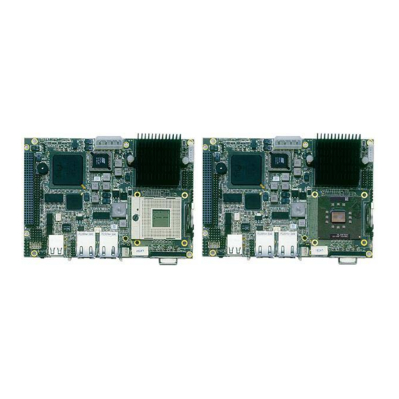
General Description HS-2616 HS-2616M The HS-2616 is an Intel® 852GME GMCH and HS-2616M is an Intel® 852GM GMCH chipset-based board designed. The HS-2616/ HS-2616M is ideal all-in-one embedded engine board. Additional features include an enhanced I/O with CF, CRT/LVDS, dual LAN, audio, 4 COM, and USB2.0 interfaces. -
Page 8: Major Features
To ensure the reliability in an unmanned or standalone system , the watchdog timer (WDT) onboard HS-2616/HS-2616M is designed with software that does not need the arithmetical functions of a real-time clock chip. If any program causes unexpected halts to the system, the onboard WDT will automatically reset the CPU or generate an interrupt to resolve such condition. - Page 9 4 x USB2.0 (2 x internal, 2 x external) 1 x IDE 1 x PS/2 for KB/MS DI/O 8-bit input/output by parallel port Display Chipset Intel® 852GME (HS-2616) Intel® 852GM (HS-2616M) Display Memory 8MB shared main memory LVDS 18-bit single/dual-channel Resolution...
-
Page 10: Board Dimensions
Ethernet Chipset Intel® 82551QM and 82562ET dual 10/100 Mbps LAN Ethernet Interface 2 x RJ-45 Board Dimensions... -
Page 11: Chapter 2 Unpacking
Chapter 2 Unpacking Opening the Delivery Package The HS-2616/HS-2616M is packed in an anti-static bag. The board has components that are easily damaged by static electricity. Do not remove the anti-static wrapping until proper precautions have been taken. Safety Instructions in front of this manual describe anti-static precautions and procedures. - Page 12 Cables Package Description QTY. 1-to-2 Mini DIN cable SPK 8-pin(2.0-pitch) phone jack x 2 COM DB9-10P (2.0-pitch) 40-pin to 44-pin IDE flat cable It is recommended that you keep all the parts of the delivery package intact and store them in a safe/dry place for any unforeseen event requiring the return shipment of the product.
-
Page 13: Chapter 3 Hardware Installation
Chapter 3 Hardware Installation This chapter provides the information on how to install the hardware using the HS-2616/HS-2616M. This chapter also contains information related to jumper settings of switch, and watchdog timer selection etc. Before Installation After confirming your package contents, you are now ready to install your hardware. -
Page 14: Board Layout
Board Layout Top Side Solder Side... -
Page 15: Jumper List
Jumper List Jumper Default Setting Setting Page Onboard LAN 2 Enabled/Disabled Select: Short 1-2 Enabled COM2 Use RS-232 or RS-485 Select: RS-232 Open Short 3-4 System Frequency Select: 400MHz JP10 Short Clear CMOS: Normal Operation Short 1-2 JP11 SDRAM Frequency Select: 266MHz Short 1-2 Connector List Connector... -
Page 16: Configuring The Cpu
Configuring the CPU The HS-2616 provides Intel® Pentium® M processor 760 2.0GHz, Pentium® M processor 745 1.8GHz, Celeron® M processor 370 1.5GHz, and Celeron® M processor 1.3GHz. The HS-2616M embedded with ULV Intel® Celeron® M processor 600MHz/512K. If you want to use 533MHz FSB processor, please set JP5/JP10, and JP5/JP10 is only for HS-2616. - Page 17 CN13: CRT Connector PIN Description PIN Description Green Blue 6 11 HSYNC VSYNC CN15/CN14: LVDS Interface Connector PIN Description PIN Description A0-/A4- A0+/A4+ A1-/A5- A1+/A5+ A2-/A6- A2+/A6+ CLK1-/CLK2- CLK1+/CLK2+ NOTE: LVDS cable should be produced very carefully. A0- & A0+ have to be fabricated in twister pair (A1- &...
-
Page 18: Pci E-Ide Drive Connector
PCI E-IDE Drive Connector CN5 is a standard 44-pin 2.0-pitch connector daisy-chain driver connector serves the PCI E-IDE drive provisions onboard the HS-2616/ HS-2616M. A maximum of two ATA/33/66/100 IDE drives can be connected to the HS-2616/HS-2616M via CN5. CN5: IDE Connector... -
Page 19: Serial Port Connectors
Serial Port Connectors The HS-2616/HS-2616M offers NS16C550 compatible UARTs with Read/ Receive 16-byte FIFO serial ports and internal 10-pin headers and RS-422/485 connector. CN3/CN2: COM 1/COM 2 Connector (5x2 Header) PIN Description PIN Description CN8: RS-485 Connector (3x2 Header, COM4) -
Page 20: Ethernet Connector
Options Settings Enabled (default) Short 1-2 Disabled Short 2-3 3.11 USB Port The HS-2616/HS-2616M provides one 8-pin connectors, at location CN4, for two USB ports, and four external USB2.0 ports at CN7. CN7: External USB2.0 Port Description Description USBD0- USBD1-... -
Page 21: Cmos Data Clear
CN4: Internal USB2.0 Port Description Description USBD2- USBD3- USBD2+ USBD3+ 3.12 CMOS Data Clear The HS-2616/HS-2616M has a Clear CMOS jumper on JP7. JP7: Clear CMOS Options Settings Normal Operation (default) Short 1-2 Clear CMOS Short 2-3 IMPORTANT: Before you turn on the power of your system, please set JP7 to Short 1-2 for normal operation. -
Page 22: Keyboard/Mouse Connectors
3.14 Keyboard/Mouse Connectors The HS-2616/HS-2616M offers CN12 for an internal 6-pin cable converter to keyboard/mouse. CN12: 6-pin Keyboard/Mouse Connector Description Keyboard Data Mouse Data Keyboard Clock Mouse Clock 3.15 System Front Panel Control The HS-2616/HS-2616M has system front panel control at location JP1. -
Page 23: Watchdog Timer
CN6: External Reset Button Description Reset Switch 3.16 Watchdog Timer Once the Enable cycle is active a Refresh cycle is requested before the time-out period. This restarts counting of the WDT period. When the time counting goes over the period preset of WDT, it will assume that the program operation is abnormal. -
Page 24: Audio Connectors
User can also use AL, 00H’s defined time for reset purposes, e.g.00H for Disable, 01H = 1sec, 02H=2sec….FFH=255sec. 3.17 Audio Connectors The HS-2616 has an onboard AC97 3D audio controller. The following tables list the pin assignments of the Line In/Audio Out connector. CN9: MIC In/Line Out Connector... - Page 25 Description Description IDE_PDD0 IDE_PDD1 IDE_PDD2 IDE_PDD11 IDE_PDD12 IDE_PDD13 IDE_PDD14 IDE_PDD15 IDE_PDCS3# IDE_PDIOR# IDE_PDIOW# +3.3V INT_IRQ15 +3.3V +3.3V RESET# IDE_PDIORDY CF_PDERQ CF_REGB IDE_ACTP# DETECT IDE_PDD8 IDE_PDD9 IDE_PDD10 Inserting a CompactFlash card into the adapter is not a difficult task. The socket and card are both keyed and there is only one direction for the card to be completely inserted.
-
Page 26: Irda Function
CN16 is a 5-pin internal IR communication connector for connection of an IrDA device. CN16: IrDA Connector Description IRRX IRTX 3.20 8-bit I/O Function The HS-2616/HS-2616M offers one 8-bit input/output port by parallel port. JP2: 8-bit Input/Output PIN Description PIN Description .286 .MODEL SMALL .DATA ;this is data area... - Page 27 wait1: loop wait1 loop begin proc near ax,@data ds,ax dx, port al, 80h dx, al ;;-------------------- ;;ROR cx, 08h al, 1 call delay dx, al loop ;;ROL push cx, 08h al, 1 dx, al call delay loop ;;-------------------- ;;-------------------- ;;ROR cx, 08h al, 1 call delay...
- Page 28 call delay dx, al loop ;;ROL push cx, 08h al, 1 dx, al call delay loop ;;-------------------- ;;-------------------- ;;ROR cx, 08h al, 1 call delay dx, al loop ;;ROL push cx, 08h al, 1 dx, al call delay loop ;;-------------------- ;;-------------------- ;;ROR cx, 08h...
- Page 29 dx, al loop ;;ROL push cx, 08h al, 1 dx, al call delay loop ;;-------------------- ;;-------------------- ;;ROR cx, 08h al, 1 call delay dx, al loop ;;ROL push cx, 08h al, 1 dx, al call delay loop ;;-------------------- ;flash LED 3 time cx, 01h al, 0ffh dx, al...
-
Page 30: Pci-104 Connector
3.21 PCI-104 Connector The HS-2616/HS-2616M provides one PCI-104 connector, at location CN1. NOTE: To integrate the PCI-104 module on to the HS-2616/HS-2616M, please use the enclosed 17mm copper stand-off to raise up the module board. CN1: PCI-104 Connector Description Description... - Page 31 Description Description INTR_D# +12V INTR_A# -12V REQC AD10 PULL VCC AD12 AD15 +3.3V +3.3V PULL VCC PULL VCC DEVSEL# IRDY# +3.3V +3.3V CBE2# AD17 AD19 AD22 +3.3V IDSEL1 IDSEL2 IDSEL3 AD25 AD28 AD27 AD31 REQA GNT0# GNTB PCICLKA PCICLKC PCIRST# INTR_B# INTR_C# INTR_C#...
- Page 32 This page is the blank page.
-
Page 33: Chapter 4 Ami Bios Setup
Chapter 4 AMI BIOS Setup The HS-2616 uses AMI BIOS for the system configuration. The AMI BIOS setup program is designed to provide the maximum flexibility in configuring the system by offering various options that could be selected for end-user requirements. This chapter is written to assist you in the proper usage of these features. -
Page 34: Using Setup
Using Setup In general, you use the arrow keys to highlight items, press <Enter> to select, use the <PageUp> and <PageDown> keys to change entries, and press <Esc> to quit. The following table provides more detail about how to navigate in the Setup program using the keyboard. Move to previous item ↑... -
Page 35: Main Menu
Main Menu Once you enter the AMI BIOS CMOS Setup Utility, the Main Menu will appear on the screen. The Main Menu allows you to select from several setup functions and two exit choices. Use the arrow keys to select among the items and press <Enter>... -
Page 36: Advanced Settings
Advanced Settings This section allows you to configure your system for the basic operation. You have the opportunity to select the system’s default speed, boot-up sequence, keyboard operation, shadowing and security. BIOS SETUP UTILITY Main Advanced PCIPnP Boot Security Chipset Power Exit Advanced Settings... - Page 37 BIOS SETUP UTILITY Main Advanced PCIPnP Boot Security Chipset Power Exit IDE Configuration OnBoard PCI IDE Controller [Both] OnBoard PCI IDE Operate Mode [Legacy Mode] Primary IDE Master : [Not Detected] Primary IDE Slave : [Not Detected] Secondary IDE Master : [Not Detected] Secondary IDE Slave : [Not Detected]...
- Page 38 BIOS SETUP UTILITY Main Advanced PCIPnP Boot Security Chipset Power Exit Hardware Health Configuration H/W Health Function [Enabled] Hardware Health Event Monitoring CPU Temperature VcoreA +3.3Vin Select Screen +5Vin Select Item - Change Field Select Field General Help Save and Exit Exit v02.59 (C)Copyright 1985-2005, American Megatrends, Inc.
-
Page 39: Advanced Pci/Pnp Settings
BIOS SETUP UTILITY Main Advanced PCIPnP Boot Security Chipset Power Exit USB Mass Storage Device Configuration USB Mass Storage Reset Delay [20 Sec] Device #1 USB Hotplug CDROM Emulation Type [Auto] Select Screen Device #2 USB Hotplug CDROM Select Item Emulation Type [Auto] - Change Field... -
Page 40: Boot Settings
Boot Settings BIOS SETUP UTILITY Main Advanced PCIPnP Boot Security Chipset Power Exit Boot Settings Boot Settings Configuration Boot Device Priority Removable Drives Select Screen CD/DVD Drives Select Item - Change Field Select Field General Help Save and Exit Exit v02.59 (C)Copyright 1985-2005, American Megatrends, Inc. -
Page 41: Security Settings
BIOS SETUP UTILITY Main Advanced PCIPnP Boot Security Chipset Power Exit Removable Drives 1st Drive [1st FLOPPY DRIVE] 2nd Device [USB:USB Hotplug FD] Select Screen Select Item - Change Field Select Field General Help Save and Exit Exit v02.59 (C)Copyright 1985-2005, American Megatrends, Inc. BIOS SETUP UTILITY Main Advanced... -
Page 42: Advanced Chipset Settings
Advanced Chipset Settings BIOS SETUP UTILITY Main Advanced PCIPnP Boot Security Chipset Power Exit Advanced Chipset Settings WARNING: Setting wrong values in below sections may cause system to malfunction. NorthBridge Configuration Select Screen SouthBridge Configuration Select Item - Change Field Select Field General Help Save and Exit... -
Page 43: Exit Options
BIOS SETUP UTILITY Main Advanced PCIPnP Boot Security Chipset Power Exit SorthBridge Chipset Configuration OnBoard AC’97 Audio [Auto] OnBoard LAN [Enabled] Select Screen Select Item - Change Field Select Field General Help Save and Exit Exit v02.59 (C)Copyright 1985-2005, American Megatrends, Inc. Exit Options BIOS SETUP UTILITY Main... - Page 44 This page is the blank page.
-
Page 45: Chapter 5 Software Utilities
It is recommended that you install the drivers matching the sections listed in this chapter. IDE Driver Installation Insert Utility CD Disk into your CD-ROM drive. The main menu will pop up as shown below. Select on the HS-2616 (or HS-7239) button to launch the installation program. - Page 46 Click on the INF Driver button to continue. Click on the appropriate OS button to continue.
- Page 47 Immediately after clicking the IDE button in Step 1, the program launches the Setup that will assist you in the installation process. Click on the Next > button to proceed. The License Agreement dialog box then appears on the screen. Choose Yes to proceed.
- Page 48 When the Readme Information dialog box pops up , just click on the Next > button to proceed. Once the Install Shield Wizard finishes updating your system, it will prompt you to restart the computer. Tick on the Yes, I want to restart my computer now followed by a click on the Finish button to reboot.
-
Page 49: Vga Driver Installation
VGA Driver Installation 5.2.1 WIN98 Insert Utility CD Disk into your CD-ROM drive. The main menu will pop up as shown below. Select on the HS-2616 (or HS-7239) button to launch the installation program. Click on the VGA Driver button to continue. - Page 50 Click on the WIN9X button to continue. When the dialog box below appears, make sure you close all other Windows applications then click on the Next > button to proceed.
- Page 51 The Intel® OEM Software License Agreement dialog box the n appears on the screen. Choose Yes to proceed. Once the setup program finishes copying files into your system, it will prompt you to restart the computer. Tick on the Yes, I want to restart my computer now followed by a click on the Finish button to reboot.
- Page 52 Please make sure you have already installed Service Pack 6.0. Insert Utility CD Disk into your CD-ROM drive. The main menu will pop up as shown below. Select on the HS-2616 (or HS-7239) button to launch the installation program. Click on the VGA Driver button to continue.
- Page 53 When the dialog box below appears, make sure you close all other Windows applications then click on the Next > button to proceed. The Intel® OEM Software License Agreement dialog box then appears on the screen. Choose Yes to proceed.
- Page 54 Finish button to reboot. 5.2.3 WIN2000/WINXP Insert Utility CD Disk into your CD-ROM drive. The main menu will pop up as shown below. Select on the HS-2616 (or HS-7239) button to launch the installation program.
- Page 55 Click on the VGA Driver button to continue. Click on the WIN2K button to continue.
- Page 56 When the dialog box below appears, make sure you close all other Windows applications then click on the Next > button to proceed. The Intel® OEM Software License Agreement dialog box appears on the screen. Choose Yes to proceed.
- Page 57 Once the setup program finishes copying files into your system, it will prompt you to restart the computer. Tick on the Yes, I want to restart my computer now followed by a click on the Finish button to reboot. Only after your computer boots will the new settings take effect.
-
Page 58: Lan Driver Installation
LAN Driver Installation 5.3.1 WIN98 Insert Utility CD Disk into your CD-ROM drive. The main menu will pop up as shown below. Select on the HS-2616 (or HS-7239) button to launch the installation program. Click on the LAN Driver button to continue. - Page 59 Click on the WIN9X button to continue. When the dialog box below appears, make sure you close all other Windows applications then click on the Install Base Driver button to proceed.
- Page 60 The Intel® OEM Software License Agreement dialog box then appears on the screen. Choose Next > to proceed. Choose the drivers install location. (ex: c:\IntelPRO) Once the setup program finishes copying files into your system, it will prompt you to restart the computer. Tick on the Restart now to reboot.
- Page 61 5.3.2 WINNT NOTE: Please make sure you have already installed Service Pack 6.0. The system automatically detects the absence of Windows NT Networking. Click on the Yes button to start installation. Tick on the Wired to the network once the following screen appears.
- Page 62 Once setup finishes the search, it will list a number of adapters for you to choose from. Press on the Have Disk button to assign the driver path location. Setup now asks you for the location of the driver. When you have entered the new driver path, press on the OK button to continue.
- Page 63 When Setup finds the information it needs about the new driver, it will display the device it found on the following screen. Please choose “Intel® PRO/100 Family Adapter”. Press on the OK button to accept and proceed. Setup then returns to Network Setup Wizard screen and displays your new Network Adapter.
- Page 64 The Network Setup Wizard then allows you to set the Network Protocols on your network. Select the appropriate protocol and then click on Next > to continue. Before Setup starts installing the components found and the settings you made, it will give you the option to proceed or go back for changes from the following screen.
- Page 65 Windows NT Setup will then need to copy files necessary to update the system information. Specify the path then press Continue. When Setup asks if you wish to change the TCP/IP settings of your system, select them appropriately. The default choice is Setup then starts the Networking installation and copies the files.
- Page 66 Setup then prompts you that it is ready to start the network. You may complete the installation thereafter. Click on Next > to continue. Assign the workgroup or domain setting of your computer. Click on Next > to continue.
- Page 67 When the dialog box below appears, it means your driver is install completed. Click Finish button to proceed. Click on the Yes button to restart your computer. The LAN driver installation for WINNT is now complete.
- Page 68 5.3.3 WIN2K/XP Insert Utility CD Disk into your CD-ROM drive. The main menu will pop up as shown below. Select on the HS-2616 (or HS-7239) button to launch the installation program. Click on the LAN Driver button to continue.
- Page 69 Click on the WIN2K button to continue. When the dialog box below appears, make sure you close all other Windows applications the click on the Install Base Driver button to proceed.
- Page 70 The Intel® OEM Software License Agreement dialog box then appears on the screen, choose Yes to proceed. Choose driver install location. (ex: c:\IntelPRO) When setup is finished, please reboot your computer to complete.
-
Page 71: Audio Driver Installation
Audio Driver Installation Insert Utility CD Disk into your CD-ROM drive. The main menu will pop up as shown below. Select on the HS-2616 (or HS-7239) button to launch the installation program. Click on the Audio Driver button to continue. - Page 72 Click on the OS button to continue. When the dialog box below appears, make sure you close all other Windows applications then click on the Next > button to proceed.
- Page 73 Once the Install Shield Wizard completes the operation and update of your AC97 driver, it will ask you to remove disks form their drives, and prompt you to restart your system. Tick on the Yes, I want to restart my computer now. Afterwards, click on the Finish button to complete the installation process.
-
Page 74: Usb2.0 Driver Installation
USB2.0 Driver Installation 5.5.1 WIN98 With the Utility CD Disk still in your CD-ROM drive, right click on “My Computer” icon from the Windows menu. Select on System Properties and then proceed to the Device Manager from the main menu. Select on Other Devices from the list of devices then double-click on PCI Universal Serial Bus. - Page 75 The PCI Universal Serial Bus Properties screen then appears, allowing you to reinstall the driver. Select Driver from the main menu to proceed. When the dialog box below appears, make sure you close all other Windows applications then click on the Next > button to proceed.
- Page 76 Tick on the “Search for a better driver” once the following screen appears, Click on the Next > to proceed. Once the program returns to the Add New Hardware Wizard screen, your specified location will appear. Press on the Next > button to continue.
- Page 77 When Setup finds the information it needs about the new driver, it will display the device it found on the following screen. Press on the Next > button to accept and proceed. Once the Install Shield Wizard completes the operation and update of your USB2.0 driver.
- Page 78 5.5.2 WIN2K With the Utility CD Disk still in your CD-ROM drive, right click on “My Computer” icon from the Windows menu. Select on System Properties and then proceed to the Device Manager from the main menu. Select on Other Devices from the list of devices then double-click on PCI Universal Serial Bus.
- Page 79 When the dialog box below appears, make sure you close all other Windows applications then click on the Next > button to proceed. Tick on the “Search for a better driver” once the following screen appears, Click on the Next > to proceed.
- Page 80 Once the program returns to the Add New Hardware Wizard screen, your specified location will appear. Press on the Next > button to continue. Choose the driver disk location.
- Page 81 Once the Install Shield Wizard completes the operation and update of your USB2.0 driver. Click on the Finish button to complete the installation process.
- Page 82 5.5.3 WINXP Insert Utility CD Disk into your CD-ROM drive. The main menu will pop up as shown below. Select on the HS-2616 (or HS-7239) button to launch the installation program. Click on the USB2.0 Driver button to continue.
- Page 83 Click on the WINXP button to continue. When the dialog box below appears, make sure you close all other Windows applications then click on the Next > button to proceed.
- Page 84 Once the Install Shield Wizard completes the operation and update of your USB2.0 driver. Click on the Finish button to complete the installation process.
Need help?
Do you have a question about the HS-2616 and is the answer not in the manual?
Questions and answers