Table of Contents
Advertisement
Quick Links
Advertisement
Table of Contents

Related Manuals for Lenovo ServeRAID M5110


Summary of Contents for Lenovo ServeRAID M5110
- Page 1 USER’S GUIDE ServeRAID M5110 SAS/SATA Controller...
- Page 2 Third Edition (March 2016) © Copyright Lenovo 2012, 2014, 2016. All rights reserved. LIMITED AND RESTRICTED RIGHTS NOTICE: If data or software is delivered pursuant a General Services Administration “GSA” contract, use, reproduction, or disclosure is subject to restrictions set forth in Contract No. GS-35F-05925.
- Page 3 M5110 SAS/SATA controller. • Chapter 2, ServeRAID Controller Hardware Installation, describes the procedures used to install the ServeRAID M5110 SAS/SATA controller, transportable memory module, and flash power module. • Chapter 3, ServeRAID M5110 SAS/SATA Controller Characteristics, provides the characteristics and technical specifications for the ServeRAID M5110 SAS/SATA controller.
- Page 4 Related Publications ServeRAID-M Device Driver Installation User’s Guide This document explains how to install the ServeRAID-M device driver for your operating system. The information in this document is independent of the back-end bus and applies to the ServeRAID-M controllers. ServeRAID-M Software User’s Guide This document explains how to use the configuration utilities to configure, monitor, and maintain your ServeRAID-M controller and the storage-related devices connected to your controller.
- Page 5 Safety Preface...
- Page 6 Preface...
- Page 7 Safety statements Preface...
- Page 8 viii Preface...
-
Page 9: Table Of Contents
1.4.1 Number of Physical Disks Supported Benefits of the SAS Interface 1.5.1 PCI Express Architecture 1-10 1.5.2 Operating System Support 1-10 Benefits of the ServeRAID M5110 SAS/SATA Controller 1-11 1.6.1 SAS Features 1-12 1.6.2 SAS Array Limitations 1-12 1.6.3 SATA III Features 1-13 1.6.4... - Page 10 Backplane on an Enclosure After Installing the Controller Chapter 3 ServeRAID M5110 SAS/SATA Controller Characteristics ServeRAID M5110 SAS/SATA Controller Descriptions 3.1.1 Board Layout and Connector Information Characteristics of the ServeRAID M5110 SAS/SATA Controller Technical Specifications 3.3.1 Controller Specifications 3.3.2 Array Performance Features 3.3.3 Fault Tolerance 3.3.4...
- Page 11 Electronic Emission Notices B.5.1 Federal Communications Commission (FCC) Statement B.5.2 Industry Canada Class A Emission Compliance Statement B.5.3 Australia and New Zealand Class A Statement B.5.4 European Union EMC Directive Conformance Statement B.5.5 Germany Class A Statement B.5.6 Japan VCCI Class A Statement B.5.7 Korea Communications Commission (KCC) Statement B.5.8...
- Page 12 Contents...
- Page 13 Figures Example of a SAS Direct-Connect Application Example of a ServeRAID Controller Configured with an Expander ServeRAID M5110 Controller Installation in a PCI Express Slot Connecting a ServeRAID M5110 Controller Internal Connector to a Drive Backplane Card Layout for the ServeRAID M5110 SAS/SATA Controller 3-2...
- Page 14 Contents...
- Page 15 ServeRAID M5110 SAS/SATA Controller Array Limitations 1-12 ServeRAID M5110 SAS/SATA Controller Specifications 1-19 ServeRAID M5110 SAS/SATA Controller Connectors ServeRAID M5110 SAS/SATA Controller Characteristics ServeRAID M5110 SAS/SATA Controller Specifications Array Performance Features Fault Tolerance Features Power Supply for the ServeRAID M5110 SAS/SATA Controller Contents...
-
Page 16: Overview
Chapter 1 Overview This chapter provides a general overview of the ServeRAID M5110 SAS/SATA controller, which has RAID control capabilities. It consists of the following sections: • Section 1.1, “Overview” • Section 1.2, “ServeRAID M5110 Controller Description and Limitations” •... -
Page 17: Serveraid M5110 Controller Description And Limitations
ServeRAID M5110 Controller Description and Limitations The ServeRAID M5110 SAS/SATA controller is a PCI-Express 3.0, half- size, half-height RAID controller based on the LSISAS2208 PCI Express- SAS/SATA I/O Processor chip. - Page 18 SATA, which enables communication with other SATA devices • Serial Management Protocol (SMP), which communicates topology management information directly with an attached SAS expander device • Serial Tunneling Protocol (STP), which enables communication with a SATA device through an attached expander ServeRAID M5110 Controller Description and Limitations...
-
Page 19: Controller Limitations
1.2.1 Controller Limitations The ServeRAID M5110 controller has the following limitations: • You can connect only one device per SAS PHY unless you use an expander • You can use a maximum cable length of six feet (using shorter cables is preferred) •... -
Page 20: Supported Raid Level Upgrades
Note: iMR RAID 5 requires purchase of the Feature on Demand (FoD) upgrade. Note: MegaRAID RAID 5/50 requires a transportable memory module (3 options). Note: MegaRAID RAID 6/60 requires a transportable memory module (3 options) and the Feature on Demand upgrade. Section 1.3.1, “Supported RAID Level Upgrades”... -
Page 21: Summary Of Raid Levels
1.3.2 Summary of RAID Levels RAID levels describe a system for ensuring the availability and redundancy of data stored on large disk subsystems. RAID 0 uses striping to provide high data throughput, especially for large files in an environment that does not require fault tolerance. RAID 1 uses mirroring so that data written to one drive is simultaneously written to another drive. -
Page 22: Configuration Scenarios
requires high reliability, high request rates, high data transfers, and medium-to-large capacity. Note: Having virtual drives of different RAID levels, such as RAID 0 and RAID 5, in the same drive group is not allowed. For example, if an existing RAID 5 virtual drive is created out of partial space in an array, the next virtual drive in the array has to be R5 only. -
Page 23: Example Of A Sas Direct-Connect Application
Figure 1.1 Example of a SAS Direct-Connect Application SAS/SATA III Device 32-Bit Memory Address/Data Flash ROM/ SAS/SATA III Device PSBRAM/ PCI Express NVSRAM RAID Controller SAS/SATA III Device Interface SAS/SATA III Device PCI Express Interface The following figure shows an example of a ServeRAID controller configured with an expander that is connected to SAS disks, SATA disks, or both. -
Page 24: Number Of Physical Disks Supported
1.4.1 Number of Physical Disks Supported Your configuration planning for your ServeRAID controller depends in part on the number of physical disks that you want to use in a RAID array. The number of drives in an array determines the RAID levels that can be supported by this controller. -
Page 25: Pci Express Architecture
PCI Express is a local bus system designed to increase data transfers without slowing down the central processing unit (CPU). You can install your ServeRAID M5110 controller PCI Express SAS/SATA controller in PCI Express computer systems with a standard bracket type. With this controller in your system, you can connect SCSI devices and SATA devices over the bus. -
Page 26: Benefits Of The Serveraid M5110 Sas/Sata Controller
Benefits of the ServeRAID M5110 SAS/SATA Controller This section provides a summary of the features and the benefits of the ServeRAID M5110 SAS/SATA controller. It contains information on SAS features, SATA features, PCI performance, integration, usability, and flexibility. The controller offers the following features: •... -
Page 27: Sas Features
1.6.1 SAS Features The following list describes the SAS features of the ServeRAID M5110 controller: • Provides eight fully independent PHYs • Supports 6.0 Gb/s SAS data transfers per PHY • Supports SSP to enable communication with other SAS devices •... -
Page 28: Sata Iii Features
Allows addressing of multiple SATA III targets through an expander • Allows multiple initiators to address a single target (in a fail-over configuration) through an expander • Displays activity and fault indicators for each PHY Benefits of the ServeRAID M5110 SAS/SATA Controller 1-13... -
Page 29: Pci Express Performance
Supports staggered spin-up • Supports hot plug 1.6.4 PCI Express Performance The following list describes the PCI Express performance features of the ServeRAID M5110 controller: • Provides a PCI Express 3.0 interface that: – Supports a dedicated PCI Express bus –... -
Page 30: Flexibility Features
Supports the external SAS Sideband signal SFF-8485 (SGPIO) interface 1.6.6 Flexibility Features These features increase the flexibility of the ServeRAID M5110 controller: • Supports a Flash ROM interface, a nonvolatile static RAM (NVSRAM) interface, and a pipelined synchronous burst SRAM (PSBRAM) interface •... -
Page 31: Drive Migration
Follow these steps to use drive roaming: Step 1. Turn off the power to the server and all physical disks, enclosures, and system components. Disconnect the power cords from the system. Step 2. Open the host system by following the instructions in the host system technical documentation. - Page 32 Close the cabinet of the host system. Step 9. Reconnect the power cords to the system. Step 10. Turn on the power to the system. The controller detects the RAID configuration from the configuration data on the drives. Benefits of the ServeRAID M5110 SAS/SATA Controller 1-17...
-
Page 33: New Drives Attached To A Serveraid Controller
1.6.9 New Drives Attached to a ServeRAID Controller In the Integrated RAID mode, when you insert a new drive with valid metadata into a ServeRAID system, the drive state of the new drive is either foreign or unconfigured bad. The specific drive state depends on the Maintain PD Fail History setting, and whether the drive had been inserted in the system before. -
Page 34: Hardware Specifications
You can use system drives as bootable drives. iMR supports up to 63 system drives and up to 16 unconfigured good drives. Hardware Specifications You can install your ServeRAID M5110 controller in a computer with a mainboard that has a PCI Express slot. Table 1.3 describes the hardware configuration features of the controller. -
Page 35: Technical Support
Direct I/O Architecture Fusion-MPT 1 In MR mode, the ServeRAID M5110 SAS/SATA controller supports cache policy, which includes write-back, write-through, adaptive read ahead, non-read ahead, read ahead, cache I/O, and direct I/O set- tings. However, in iMR mode, the controller does not support these cache policy settings. -
Page 36: Chapter 2 Serveraid Controller Hardware Installation
The ServeRAID M Documentation CD containing the documentation • The necessary internal cables • SAS physical disks or SATA physical disks (Mechanical or Solid State Devices, SSDs) Note: For optimal performance, use an uninterruptible power supply. ServeRAID M5110 SAS/SATA Controller x User’s Guide... -
Page 37: Quick Installation
Quick Installation The following steps are for quick installation of your controller. These steps are for experienced computer users/installers. Section 2.3, “Detailed Installation,” contains the steps for all others to follow. Step 1. Review all safety information provided with the server; then, turn off the power to the server and all of the attached devices, and unplug the server and the device power cords. - Page 38 Step 3. Review the Controller Connectors Refer to Chapter 3, “ServeRAID M5110 SAS/SATA Controller Characteristics” for a diagram of the ServeRAID M5110 controller with its connectors. Step 4. Review the Controller Limitations Review Section 1.2.1, “Controller Limitations”...
-
Page 39: Serveraid M5110 Controller Installation In A Pci Express Slot
Figure 2.1 ServeRAID M5110 Controller Installation in a PCI Express Slot Bracket Screw Press Here Press Here PCI Express Edge of Motherboard 3_00793-00 Step 6. Connect the Controller to the Drive Backplane on an Enclosure Use cables to connect the controller to the drive backplane of an enclosure that contains SAS devices, SATA devices, or both. - Page 40 turned on to the devices, the computer might not recognize the devices. For the United Extensible Firmware Interface (UEFI), no BIOS message displays. Press F1 to enter System Setup. Refer to your system user’s guide for specific configuration information. Under other interfaces or operating systems, a BIOS message appears during boot.
-
Page 41: Connecting A Serveraid-M5110 Sas/Sata Controller To A Drive Backplane On An Enclosure
Connecting a ServeRAID-M5110 SAS/SATA Controller to a Drive Backplane on an Enclosure This section describes how to connect the ServeRAID M5110 SAS/SATA controller by cable to the drive backplane on an enclosure. The enclosure can contain SAS drives and SATA drives. -
Page 42: After Installing The Controller
Figure 2.2 Connecting a ServeRAID M5110 Controller Internal Connector to a Drive Backplane 3_01278-00 Step 6. Replace the server cover. Step 7. Slide the server into the rack. Step 8. Reconnect the power cords and any cables that you removed. -
Page 43: Serveraid M5110 Sas/Sata Controller Characteristics
Chapter 3 ServeRAID M5110 SAS/SATA Controller Characteristics This chapter describes the characteristics of the ServeRAID M5110 SAS/SATA controller. It consists of the following sections: • Section 3.1, “ServeRAID M5110 SAS/SATA Controller Descriptions” • Section 3.2, “Characteristics of the ServeRAID M5110 SAS/SATA Controller”... -
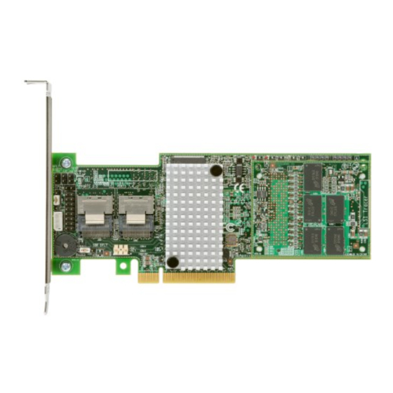
Page 44: Card Layout For The Serveraid M5110 Sas/Sata Controller
Figure 3.1 Card Layout for the ServeRAID M5110 SAS/SATA Controller J1A1 J1A2 J1A3 J5A1 J6A1 J1A4 J1A5 J1A8 J2B1 J2B2 J1A7 J5B1 J1B1 J2B4 Table 3.1 ServeRAID M5110 SAS/SATA Controller Connectors Connector Description Type Comments J1A1 Global drive fault 2-pin... - Page 45 Table 3.1 ServeRAID M5110 SAS/SATA Controller Connectors Connector Description Type Comments J1A4 Activity LED header 2-pin Connects to an LED that connector indicates activity on the drives connected to the controller. J1A4 J1A5 Individual PHY and 2x8-pin Connects to an LED that...
- Page 46 Table 3.1 ServeRAID M5110 SAS/SATA Controller Connectors Connector Description Type Comments J1A8 O Mode Selection 2-pin Installing this jumper causes the header RAID controller to run in I2O Mode. The default mode of operation is without the shunt. Note: The MegaRAID firmware...
-
Page 47: Characteristics Of The Serveraid M5110 Sas/Sata Controller
Asynchronous connector Receiver/Transmitter (UART) connector for the Expander Characteristics of the ServeRAID M5110 SAS/SATA Controller Table 3.2 shows the general characteristics of the ServeRAID M5110 SAS/SATA controller. Table 3.2 ServeRAID M5110 SAS/SATA Controller Characteristics Flash Serial SCSI EEPROM SAS Data Transfers... -
Page 48: Technical Specifications
Taiwan BSMI • Japan VCCI In addition, the controller meets the requirements of CISPR Class B. The ServeRAID M5110 SAS/SATA controller is CSA C22.2 No. 60950-1, UL 60950-1 First Edition listed Accessory, UL file number E257743. 3.3.1 Controller Specifications Table 3.3 lists the specifications for the ServeRAID M5110 SAS/SATA controller. -
Page 49: Array Performance Features
Table 3.3 ServeRAID M5110 SAS/SATA Controller Specifications Specification ServeRAID M5110 SAS/SATA Controller • Up to 8 GT/s (1 GB/s) per lane PCI Express Bus Data Transfer Rate • x8 lane width • Up to 2 GB/s per direction for SAS x4 cards... -
Page 50: Fault Tolerance
3.3.3 Fault Tolerance Table 3.5 shows the fault tolerance features of the ServeRAID M5110 SAS/SATA controller. Table 3.5 Fault Tolerance Features Specification ServeRAID M5110 SAS/SATA Controller Support for SMART Drive Failure Detection Automatic Drive Rebuild Using Hot Spares Automatic Parity Generation and Checking Yes The Self Monitoring Analysis and Reporting Technology (SMART) detects up to 70 percent of all predictable drive failures. -
Page 51: Operating And Non-Operating Conditions
Temperature range: −30 °C to +80 °C 3.3.6 Safety Characteristics The ServeRAID M5110 SAS/SATA controller meets or exceeds the requirements of UL flammability rating 94 V0. Each bare board is also marked with the supplier name or trademark, type, and UL flammability rating. -
Page 52: Appendix A Getting Help And Technical Assistance
Appendix A Getting Help and Technical Assistance ServeRAID M5110 SAS/SATA Controller User’s Guide... -
Page 53: Before You Call
A.1 Before You Call Getting Help and Technical Assistance... -
Page 54: Using The Documentation
A.2 Using the Documentation A.3 Getting Help and Information from the World Wide Web Using the Documentation... -
Page 55: Software Service And Support
A.4 Software Service and Support A.5 Hardware Service and Support Getting Help and Technical Assistance... -
Page 56: Taiwan Product Service
A.6 Taiwan Product Service Taiwan Product Service... -
Page 57: Appendix B Notices
Appendix B Notices ServeRAID M5110 SAS/SATA Controller User’s Guide... -
Page 58: Trademarks
B.1 Trademarks Notices... -
Page 59: Important Notes
B.2 Important Notes Important Notes... -
Page 60: Recycling Information
B.3 Recycling Information B.4 Telecommunication Regulatory Statement B.5 Electronic Emission Notices Notices... - Page 61 B.5.1 Federal Communications Commission (FCC) Statement B.5.2 Industry Canada Class A Emission Compliance Statement B.5.3 Australia and New Zealand Class A Statement Electronic Emission Notices...
- Page 62 B.5.4 European Union EMC Directive Conformance Statement Notices...
- Page 63 B.5.5 Germany Class A Statement Electronic Emission Notices...
- Page 64 B.5.6 Japan VCCI Class A Statement Notices...
- Page 65 B.5.7 Korea Communications Commission (KCC) Statement B.5.8 Russia Electromagnetic Interference (EMI) Class A Statement B.5.9 People's Republic of China Class A Electronic Emission Statement Electronic Emission Notices...
- Page 66 B.5.10 Taiwan Class A Compliance Statement B-10 Notices...
- Page 67 A SAS device installed outside the computer cabinet. These devices are device connected using specific types of shielded cables. Fusion-MPT Fusion-MPT (Message Passing Technology) architecture consists of architecture several main elements: Fusion-MPT firmware, the Fibre Channel and ServeRAID M5110 SAS/SATA Controller User’s Guide...
- Page 68 SCSI hardware, and the operating system level drivers that support these architectures. Fusion-MPT architecture offers a single binary, operating system driver that supports both Fibre Channel and SCSI devices. host The computer system in which a storage controller is installed. It uses the storage controller to transfer information to and from devices attached to the SCSI bus.
- Page 69 a unifying I/O architecture for various systems: desktops, workstations, mobile, server, communications, and embedded devices. peripheral A piece of hardware (such as a video monitor, drive, printer, or CD-ROM) devices used with a computer and under the control of the computer. SCSI peripherals are controlled through a ServeRAID SAS/SATA controller (host controller).
- Page 70 The ServeRAID M5110 SAS/SATA controller is a versatile controller that provides the backbone of both server and high-end workstation environments. Each port on the RAID controller supports SAS devices and/or SATA III devices. SAS device Any device that conforms to the SAS standard and is attached to the SAS bus by a SAS cable.
- Page 71 therefore, may have several stripes. The amount of space consumed by a stripe is the same on each disk included in the stripe. The portion of a stripe that resides on a single disk is a stripe element. Striping by itself does not provide data redundancy;...
- Page 72 P/N: 81Y1007...
Need help?
Do you have a question about the ServeRAID M5110 and is the answer not in the manual?
Questions and answers