
Related Manuals for Riello RL 300/B MZ


Summary of Contents for Riello RL 300/B MZ
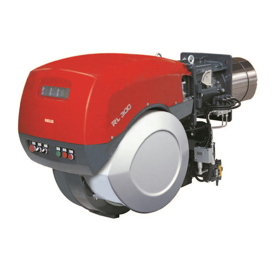
- Page 1 Installation, use and maintenance instructions Kerosene and gas oil burners Two-stage operation CODE MODEL TYPE 20034242 RL 300/B MZ 966 T 20034244 RL 400/B MZ 967 T 20035745 (4) - 04/2012...
-
Page 3: Table Of Contents
Contents Declaration....................................3 Information and general warnings............................4 Information about the instruction manual ........................4 2.1.1 Introduction.................................. 4 2.1.2 General dangers................................4 2.1.3 Danger: live components............................. 4 Guarantee and responsibility............................5 Guidance for the use of bio fuel blends up to 10%...................... 5 2.3.1 Information and general instructions ........................... - Page 4 Contents Electrical system..................................22 Notes on safety for the electrical wiring ........................22 Electrical connections ..............................22 Start-up, calibration and operation of the burner ........................23 Notes on safety for the first start-up ...........................23 Burner firing ................................23 Burner calibration ...............................23 7.3.1 Combustion head setting ............................23 7.3.2 1st and 2nd stage nozzles ............................23 7.3.3...
-
Page 5: Declaration
The quality is guaranteed by a quality and management system certified in accordance with UNI EN ISO 9001. Manufacturer's Declaration RIELLO S.p.A. declares that the following products comply with the NOx emission limits specified by German standard “1. BImSchV reliese 26.01.2010”. -
Page 6: Information And General Warnings
Information and general warnings Information and general warnings Information about the instruction manual 2.1.1 Introduction 2.1.3 Danger: live components The instruction manual supplied with the burner: This symbol indicates operations which, if not car- is an integral and essential part of the product and must not ried out correctly, lead to electric shocks with le- be separated from it;... -
Page 7: Guarantee And Responsibility
All components within the hydraulic circuit suitable for manual, operating negligence, incorrect installa- bio fuel use and supplied by Riello will be identified as Bio com- tion and carrying out of non authorised modifica- patible. No warranty is given in relation to the use of components... -
Page 8: Information And General Instructions
If this is not completed then due to the hydro- In no event shall Riello (and its subsidiaries) be liable for any in- scopic nature of Bio fuel, it will effectively clean the tank,... -
Page 9: Safety And Prevention
Safety and prevention Safety and prevention Introduction The burners have been designed and built in compliance with the type and pressure of the fuel, the voltage and frequency of the current regulations and directives, applying the known technical electrical power supply, the minimum and maximum deliveries for rules of safety and envisaging all the potential danger situations. -
Page 10: Technical Description Of The Burner
3 / 220V / 60Hz - 3N / 380V / 60Hz Auxiliary voltage : 230/50/60 230V / 50-60Hz 110/50/60 110V / 50-60Hz 3/400/50 230/50-60 BASIC DESIGNATION EXTENDED DESIGNATION Models available Designation Electrical supply Starting Code RL 300/B MZ 3/230-400/50 Direct 20034242 RL 400/B MZ 3/400/50 Star/Delta 20034244 20035745... -
Page 11: Technical Data
Technical description of the burner Technical data Model RL 300/B MZ RL 400/B MZ Type 966 T 967 T Output stage 1250 - 3550 2000 - 4450 Delivery Mcal/h 1075 - 3053 1720 - 3827 kg/h 105 - 301 169 - 378... -
Page 12: Electrical Data
Technical description of the burner Electrical data Motor IE1 Model RL 300/B MZ RL 400/B MZ Electrical supply V/Ph/Hz 230-400/3/50 400/3/50 Auxiliary power supply V/Ph/Hz 230/1/50 Electric motors 2860 2800 4500 7500 230/400 15.8/9.1 15.6 Pomp motor 1100 220/380 4,7 - 2,7... -
Page 13: Overall Dimensions
The overall dimensions of the burner when open are indicated by L and R. Bear in mind that inspection of the combustion head requires the burner to be opened by rotating the rear part on the hinge. D3319 Fig. 1 RL 300/B MZ 1325 1175 1055 RL 400/B MZ 1325... -
Page 14: Test Boiler
Technical description of the burner 4.7.1 Test boiler The firing rate was set in relation to special test boilers in accord- ance with the methods defined in EN 267 standards. Fig. 3 indicates the diameter and length of the test combustion chamber. -
Page 15: Description Of Panel Board
4 - Screws to secure the burner flange to the boiler: M 18 x 70 Bio blend, it will be essential to use flexible oil 1 - Instruction booklet lines suitable for bio fuel use. Please contact Riello for further information. 1 - Spare parts list WARNING 20035745... -
Page 16: Installation
In the event of doubt, do not use the burner; contact the supplier. CAUTION The packaging elements (wooden cage or card- RIELLO S.p.A. board box, nails, clips, plastic bags, etc.) must not 0036 I−37045 Legnago (VR) -
Page 17: Installer/Servicer Notes For The Use Of Gas Oil With Bio Blends Up To 10
The burner hydraulic components and flexible oil lines must burner technical manual). be suitable for bio fuel use (check with Riello if in doubt). If a Bio blend is in use the installer must seek information Riello have carefully chosen the specification of the bio... -
Page 18: Boiler Plate
Boiler plate Drill the combustion chamber locking plate as shown in Fig. 10. The position of the threaded holes can be marked using the ther- mal screen supplied with the burner. RL 300/B MZ M 18 RL 400/B MZ M 18 Tab. -
Page 19: Nozzle Installation
5.10.3 Nozzle assembly In order to guarantee that emissions do not vary, recommended and/or alternative nozzles specified by Riello in the Instruction Fit two nozzles with the box spanner 1)(Fig. 13) (16 mm), after and warning booklet should be used. -
Page 20: Position Of Electrodes
Installation 5.11 Position of electrodes Make sure that the electrodes are positioned as shown in Fig. 14. Measures must be respected. WARNING 4 ÷ 4 , 5 D3323 Fig. 14 20035745... -
Page 21: Gas Oil Supply
You are advised to use additional filters on the fuel Key (Fig. 15) supply line. H Pump/Foot valve height difference Riello recommends a good quality fuel filter at the L Piping length tank (Fig. 15 - Fig. 16) and a secondary filter CAUTION ø... -
Page 22: 5.12.3 Single-Pipe Circuit
Installation 5.12.3 Single-pipe circuit In order to obtain single-pipe working it is necessary to unscrew the return hose, remove the by-pass screw 6)(Fig. 17) and then screw the plug 7). The distance “P” must not exceed 10 meters in order to avoid subjecting the pump's seal to excessive strain;... -
Page 23: Pump
If the pump fails to prime at the first starting of the burner and the lines suitable for bio fuel use. burner locks out, wait approx. 15 seconds, reset the burner, and Please contact Riello for further information. WARNING then repeat the starting operation as often as required. -
Page 24: Electrical System
Electrical connections Electrical wiring must be made in accordance with the regulations currently in force in the country of destination and by qualified personnel. Riello S.p.A. declines all liability for modifications WARNING or connections other than those shown on these diagrams. -
Page 25: Start-Up, Calibration And Operation Of The Burner
Find the delivery of the two 30 GPH nozzles in (Tab. F at D3324 page 17): 1455.9 + 1455.9 = 2911.8 kW. RL 300/B MZ RL 400/B MZ Diagram (Fig. 21) indicates that for a delivery of 2911.8 kW the burner requires the combustion head to be set to approx. -
Page 26: Servomotor
Start-up, calibration and operation of the burner Servomotor The servomotor (Fig. 22), by means of connection mechanisms, simultaneously regulates air pressure and delivery and the flow of fuel in use. It features adjustable cams that operate as many switches. Cam 1: blue limits servomotor travel to 0°... -
Page 27: Air Pressure Switch - Co Check
Start-up, calibration and operation of the burner Air pressure switch - CO check Adjust the air pressure switch after having performed all other burner adjustments with the air pressure switch set to the start of the scale (Fig. 25). With the burner running at maximum output, measure CO emis- sion in the flue gases, then progressively obstruct the air intake with the aid of the regulating grille 1)(Fig. -
Page 28: Steady State Operation
Start-up, calibration and operation of the burner 7.8.2 Steady state operation Systems not equipped with control device TR (jumper wire installed) System equipped with one control device TR The burner is fired as described in the case above. Once the starting cycle has come to an end,set 0-auto-man se- If the temperature or pressure increase until control device TL lector to auto the command of the 2 stage solenoid valve pass-... -
Page 29: Maintenance
Maintenance Maintenance Notes on safety for the maintenance The periodic maintenance is essential for the good operation, Before carrying out any maintenance, cleaning or checking oper- safety, yield and duration of the burner. ations: It allows you to reduce consumption and polluting emissions and to keep the product in a reliable state over time. -
Page 30: Burner Start-Up Cycle Diagnostics
Maintenance If the problem lies in the suction line, check to make sure that the Fuel tank filter is clean and that air is not entering the piping. If water or contamination is present within the fuel tank, it is es- sential that this is removed before the equipment is to be used. -
Page 31: Software Diagnostics
Maintenance Once the button is released, the red LED will flash intermit- 8.4.3 Software diagnostics tently with a higher frequency: only now can the optical link Reports burner life by means of an optical link with the PC, indi- be activated. cating hours of operation, number and type of lock-outs, serial Once the operations are done, the control box’s initial state must number of control box etc ... -
Page 32: Faults - Possible Causes - Solutions
Faults - Possible causes - Solutions Faults - Possible causes - Solutions Find a list of faults, causes and possible solutions for a set of failures that may occur and result in irregular burner operation or no functioning at all. If a burner malfunction is detected, first of all: •... - Page 33 Faults - Possible causes - Solutions SIGNAL FAULT POSSIBLE CAUSE SOLUTION The burner does Control device TR does not close Adjust or replace not pass to 2nd Defective control box Replace stage 2nd stage solenoid valve coil defective Replace Piston jammed in valve unit Replace entire unit Fuel passes to 2nd Low pump pressure...
-
Page 34: Appendix - Accessories (Optional)
Appendix - Accessories (optional) Appendix - Accessories (optional) SOUND PROOFING BOX SPACER KIT If noise emission needs reducing even further, sound-proofing If burner head penetration into the combustion chamber needs boxes is available. reducing, varying thickness spacers are available, as given in the following table. -
Page 35: B Appendix - Electrical Panel Layout
Appendix - Electrical panel layout Appendix - Electrical panel layout Index of layouts References layout Layout of unifilar output (RL 300/B MZ) (RL 400/B MZ) Functional diagram (RL 300/B MZ) Star/delta starter operational layout (RL 400/B MZ) RMO 88... operational layout RMO 88... - Page 36 Appendix - Electrical panel layout 20035745...
- Page 37 Appendix - Electrical panel layout 20035745...
- Page 38 Appendix - Electrical panel layout 20035745...
- Page 39 Appendix - Electrical panel layout 20035745...
- Page 40 Appendix - Electrical panel layout 20035745...
- Page 41 Appendix - Electrical panel layout 20035745...
- Page 42 Appendix - Electrical panel layout 20035745...
- Page 43 Appendix - Electrical panel layout Key to electrical layout Control box Fan motor thermal cut-out Pump motor thermal cut-out Auxiliary fuse Signal light for burner on Signal light for motor trip Star-powered/delta-powered line contactor Pump motor contactor Star-powered/delta-powered starter /delta contactor Star-powered/delta-powered starter /star-powered con- tactor KST1 Star-powered/delta -powered starter timer...
- Page 44 RIELLO S.p.A. I-37045 Legnago (VR) Tel.: +39.0442.630111 http:// www.rielloburners.com Subject to modifications...
Need help?
Do you have a question about the RL 300/B MZ and is the answer not in the manual?
Questions and answers