Table of Contents
Advertisement
Quick Links
Advertisement
Table of Contents

Related Manuals for Crestron TPMC-CH-IMC


Summary of Contents for Crestron TPMC-CH-IMC
- Page 1 Crestron TPMC-CH-IMC Interface Module Operations Guide...
- Page 2 This document was prepared and written by the Technical Documentation department at: Crestron Electronics, Inc. 15 Volvo Drive Rockleigh, NJ 07647 1-888-CRESTRON All brand names, product names and trademarks are the property of their respective owners. ©2005 Crestron Electronics, Inc.
-
Page 3: Table Of Contents
Crestron TPMC-CH-IMC Contents Interface Module: TPMC-CH-IMC Introduction...1 Features & Functions...1 Specifications...3 Physical Description ...4 Industry Compliance...8 Setup...8 Network Wiring ...8 CAT5 Wiring ...10 Hardware Hookup...11 Problem Solving...13 Troubleshooting...13 Further Inquiries ...14 Future Updates...14 Return and Warranty Policies ...15 Merchandise Returns / Repair Service ...15 CRESTRON Limited Warranty ...15... -
Page 5: Interface Module: Tpmc-Ch-Imc
(via BNC) and balanced/unbalanced audio signals to be connected to the touchpanel’s CAT5 inputs and outputs. This device can also be used to convert sources to CAT5 for use with other Crestron CAT5 devices such as the CNXRMCLV Enhanced Room Solution Box. - Page 6 Interface Module The following block diagram illustrates the function of the TPMC-CH-IMC. Block Diagram of the TPMC-CH-IMC 2 • Interface Module: TPMC-CH-IMC Crestron TPMC-CH-IMC Operations Guide - DOC. 6345...
-
Page 7: Specifications
41º to 122º F (5º to 50º C), 10 to 90% Relative Humidity, non-condensing Height: 1.29 in (3.26 cm) Width: 7.30 in (18.54 cm) Depth: 3.95 in (10.02 cm) Weight: 9.7 oz (0.28 kg) Interface Module: TPMC-CH-IMC • 3 balanced... -
Page 8: Physical Description
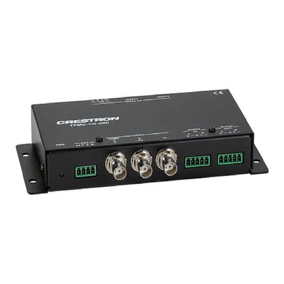
Interface Module Physical Description The TPMC-CH-IMC, shown in the following diagram, is supplied with the TPMC-15-CH and TPMC-17-CH tilt touchpanel media centers. The module is housed in a black enclosure with a silk-screened top panel. A Light Emitting Diode (LED) indicating power, a network connector, and connectors for video input, audio input, and audio output are located on one side of the unit. - Page 9 This 4-position mini-terminal block connector is used to connect to other Cresnet peripherals in a system. Another NET connector is located on the other side of the module. Data and power for the TPMC-CH-IMC are provided via either connection. If making network connections to a control system or Cresnet peripherals, refer to “Network Wiring”...
- Page 10 The 5-position mini-terminal block connector mates with the included connector and provides balanced and/or unbalanced microphone output. Description of the pinouts is shown in the following table. AUDIO OUT Pinouts DESCRIPTION Right Negative 6 • Interface Module: TPMC-CH-IMC Left Positive Left Negative Ground Right Positive Left Positive...
- Page 11 BLUE WHITE/BLUE GREEN WHITE/BROWN BROWN Indicator This LED, located on the front panel, illuminates when 24 VDC is supplied to the TPMC-CH-IMC via the NET port. Operations Guide - DOC. 6345 S-VIDEO COMPONENT COMPOSITE + Composite + Luminance - Composite...
-
Page 12: Industry Compliance
Interface Module Industry Compliance As of the date of manufacture, the TPMC-CH-IMC has been tested and found to comply with specifications for CE marking and standards per EMC and Radiocommunications Compliance Labelling. NOTE: This device complies with part 15 of the FCC rules. Operation is... - Page 13 Cresnet power usage of each network unit to be daisy-chained must be added together to determine the Cresnet power usage of the entire chain. If the unit is a home-run from a Crestron system power supply network port, the Cresnet power usage of that unit is the Cresnet power usage of the entire run.
-
Page 14: Cat5 Wiring
If the AUDIO OUT port connects to a device with balanced inputs or no device is connected, the maximum cable length for CAT5 audio is 1000 feet. For more information, refer to the latest version of the Crestron CAT5 Wiring Reference Guide (Doc. 6137). -
Page 15: Hardware Hookup
A triamese cable that is included with the touchpanel has an RJ-45 connector with a blue cover to match the blue label on the TPMC-CH-IMC and an RJ-45 connector with a red cover to match the red label on the TPMC-CH-IMC. The cable also has a 4-position mini- terminal block connector for making a network connection between the touchpanel and the TPMC-CH-IMC. - Page 16 Interface Module Wiring for Audio Input: Unbalanced (left) and Balanced (right) Left Shield Right Shield Wiring for Audio Output: Unbalanced (left) and Balanced (right) Shield Shield 12 • Interface Module: TPMC-CH-IMC Shield Jumpers Right Left Crestron TPMC-CH-IMC Shield Right Left...
-
Page 17: Problem Solving
Crestron TPMC-CH-IMC Problem Solving Troubleshooting The following table provides corrective action for possible trouble situations. If further assistance is required, please contact a Crestron customer service representative. TPMC-CH-IMC Troubleshooting TROUBLE Touchpanel does not function. Video window on touchpanel has no display. -
Page 18: Further Inquiries
Crestron website (www.crestron.com) for a listing of Crestron worldwide offices. You can also log onto the online help section of the Crestron website to ask questions about Crestron products. First-time users will need to establish a user account to fully benefit from all available features. -
Page 19: Return And Warranty Policies
(property or economic damages inclusive) arising from the sale or use of this equipment. CRESTRON is not liable for any claim made by a third party or made by the purchaser for a third party. - Page 20 Crestron Electronics, Inc. Operations Guide - DOC. 6345 15 Volvo Drive Rockleigh, NJ 07647 (2012969) Tel: 888.CRESTRON 04.05 Fax: 201.767.7576 Specifications subject to www.crestron.com change without notice.
Need help?
Do you have a question about the TPMC-CH-IMC and is the answer not in the manual?
Questions and answers