Table of Contents
Advertisement
Quick Links
Advertisement
Table of Contents

Related Manuals for PXM PX787


Summary of Contents for PXM PX787
- Page 1 PX787 DMX / DALI 1x User manual...
-
Page 2: Table Of Contents
4.7.1 Dark mode......................19 4.7.2 Reboot the device.................... 19 4.7.3 Restore default settings..................20 4.8 Setting the display contrast..................21 4.9 Menu scheme in PX787..................22 5 Connecting to the PC................23 5.1 Change of the computer network configuration..........24 5.2 Connecting converter directly to the PC...............27 5.3 Connecting the converter using a router..............27... - Page 3 10 DMX signal connecting.................56 11 Connection scheme................57 12 Dimensions.....................58 13 Technical data..................59 Manufacturer reserves the right to make modifications in order to improve device operation. PXM Marek Żupnik sp.k. Podłęże 654 tel. +48 12 385 83 06 32-003 Podłęże mail: info@pxm.pl Rev.1-3 BDO register number 000005972 www.pxm.pl...
-
Page 4: Description
DMX / DALI 1x is an advanced converter that allows to combine lighting installations based on the DALI protocol with DMX-512 control system. Using the PX787, you can connect devices working in the DALI protocol to the controller sending the DMX-512 signal. -
Page 5: Safety Conditions
* - support for external keys is available from serial number 21030041 Safety conditions PX787 is a device powered with safe voltage 12 – 24V DC; however, during its installation and use the following rules must be strictly observed: 1. The device may only be connected to 12 – 24V DC with current- carrying capacity compatible with technical data. -
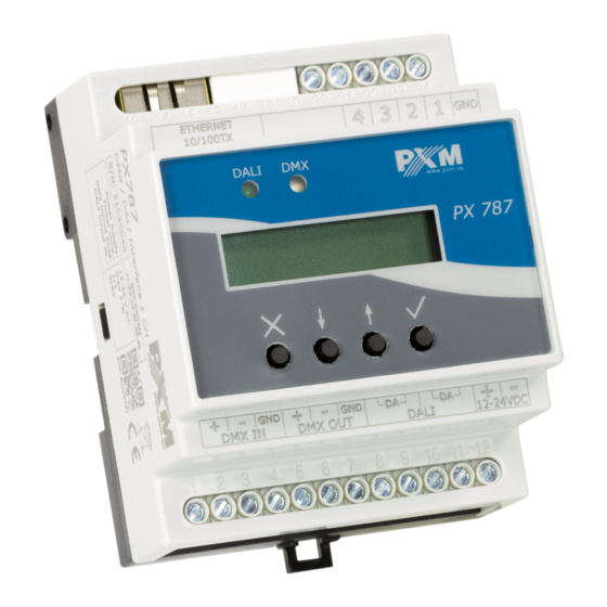
Page 6: Connectors And Control Elements
9. The device cannot be used in places with temperature lower than +2°C or higher than +40°C. 10. Clean with damp duster only. Connectors and control elements digital inputs Ethernet port signaling diodes PX787 DMX 2 DALI display 192.168.0.50 programming keyes power supply DMX output 12 - 24V DC DMX input... -
Page 7: Programming Using Buttons
Programming using buttons 4.1 Navigating the menu (escape) - allows to exit the parameter being programmed ✕ without saving any changes or to move to a higher menu level ↓ (previous) - scrolls the menu up or reduces the values to be set ↑... -
Page 8: Description Of Information Parameters
• converter model and current IP address (if an address is provided by DHCP, an asterisk “*” is added), number of ballasts found by PX787 (e.g. 8), • converter serial number and version number of the software installed, •... -
Page 9: Dmx Dali Settings
Conv. enabled NO<- NOTE! After connecting the PX787 to an existing installation (the ballasts are addressed), select the [Search] option – it will not change the ballasts addresses. If the ballasts in the installation do not have assigned addresses –... -
Page 10: No Signal Function
ENTER PX787 DMX 2 DALI DALI bus 192.168.0.50 NEXT ENTER ENTER DMX -> DALI Conv. enabled Conv. enabled YES<- NEXT Conv. enabled NO<- NOTE! After restarting the device, signal conversion is enabled. 4.4.2 No Signal function In the [No DMX signal] menu, you can set the behavior of the converter in case of DMX signal loss. - Page 11 ENTER PX787 DMX 2 DALI DALI bus 192.168.0.50 NEXT ENTER DMX -> DALI Conv. enabled NEXT No DMX signal ENTER No DMX signal ON<- NEXT No DMX signal OFF<- NEXT No DMX signal Value HOLD<- 0<- NEXT PREV ENTER ENTER...
-
Page 12: Assigning Dmx Channels To Dali Addresses
4.4.3 Assigning DMX channels to DALI addresses In order to assign DMX addresses to DALI addresses, enter → the [DMX DALI] option. The selected DMX address can be assigned to a maximum of 4 ballasts or one group or broadcast address. In this menu you can assign a DMX channel to: [DALI Broadcast] –... - Page 13 ◦ [Clear following] – starting from the current DALI address it will remove the next assigned DMX channels to the DALI addresses For example, by setting to the DALI address A04, the execution of the [Clear following] option will work as follows: DALI address DMX channel ◦...
- Page 14 ◦ [Del. duplicates] – will remove assigned DMX addresses from all groups where the same DMX address was used as in the selected group (operation similar to the example [Dali Address]). ENTER PX787 DMX 2 DALI DALI bus 192.168.0.50 NEXT ENTER DMX ->...
-
Page 15: Digital Inputs
4.5 Digital inputs Starting from the device with the serial number 21030041, support for up to 4 digital inputs is available. In the [Inputs] menu, each of the digital inputs can be individually assigned its operating parameters: [Active] – defines whether the digital input is to be active, two states •... - Page 16 [Dimming] – if this option is enabled, holding down the button will • lighten or darken, two states are YES / NO. Fade rate affects the smoothness of brightening and dimming. ENTER PX787 DMX 2 DALI DALI bus 192.168.0.50 2 x NEXT ENTER...
-
Page 17: Converter Network Settings
4.6 Converter network settings PX787 gives you the ability to change network settings in the [Network config.] menu. The following parameters can be changed: static IP address [IP address], subnet mask [Subnet mask] (subnet mask edited by changing the CIDR in the range of 1 – 30), default gateway [Gateway address] and enabling On or disabling Off support [DHCP]. -
Page 18: Other Parameters
NOTE! After making changes to the network settings, restart the device in the [Management] menu by selecting [Reboot device] – according to the diagram below. The device will restart. ENTER PX787 DMX 2 DALI DALI bus 192.168.0.50 4 x NEXT... -
Page 19: Dark Mode
When [Dark mode] is turned on, after 10 seconds of inactivity, the display and indicator lights turn off. The device continues to work without interfering with other parameters. To restore the backlight, press any key. ENTER PX787 DMX 2 DALI DALI bus 192.168.0.50 4 x NEXT... -
Page 20: Restore Default Settings
Dark mode: OFF Input 1 – 4: OFF • clearing the DALI line addressing settings table • deleting saved ballasts from the list • ENTER PX787 DMX 2 DALI DALI bus 192.168.0.50 4 x NEXT ENTER Management Dark mode 2 x NEXT... -
Page 21: Setting The Display Contrast
/ ↓ ↑ keys to adjust the value to suit your needs). To exit [LCD contrast] menu, press the ✓ key. ~10 x X PX787 DMX 2 DALI LCD contrast 1792.168.0.50 NEXT... -
Page 22: Menu Scheme In Px787
4.9 Menu scheme in PX787 ENTER ENTER PX787 DMX 2 DALI DALI bus Found ballasts 192.168.0.50 NEXT NEXT ENTER DMX -> DALI Conv. enabled Initialize NEXT NEXT ENTER No DMX signal No DMX signal Search ON<- NEXT NEXT NEXT ENTER... -
Page 23: Connecting To The Pc
If the converter obtained the IP address from the DHCP server, unplugging the network cable will cause the loss of the assigned IP address. If PX787 is reconnected to the network, it will try to get a new address from the DHCP server, if it fails to receive the address, it will work according to the saved static settings. -
Page 24: Change Of The Computer Network Configuration
5.1 Change of the computer network configuration The procedure for changing the computer network configuration varies depending on the operating system. Windows ® 7 system is an example here. Change of the computer network configuration in the Windows ® 7 operating system in done in the following : 1. - Page 25 6. Right-click on [Połączenie lokalne] (Local area connection) and choose the [Properties] 7. In the new window that appears, select [Internet Protocol Version 4 (TCP/IPv4)] and then press properties...
- Page 26 8. In the next window, select [Use the following IP address:] To connect directly (computer – driver) with a controller that has a default configuration, use the sample settings: IP address: 192.168.0.51 Subnet mask: 255.255.255.0 Default gateway: 192.168.0.1...
-
Page 27: Connecting Converter Directly To The Pc
IP : 192.168.0.51 Mask : 255.255.255.0 DHCP : Off NOTE! Remember that the PX787 converter and the computer should be in the same network and there is no conflict of IP addresses. 5.3 Connecting the converter using a router When connecting the converter to the router, there are two options for network settings. -
Page 28: Automatic Addressing
IP address. 5.3.1 Automatic addressing The diagram below shows the connection of the device with the router on which the DHCP server operates: PX787 network settings downloaded automatically from the DHCP server: DHCP : On Router with a DHCP server running PX787 DMX 2 DALI 172.20.90.243*... -
Page 29: Static Addressing
IP : 192.168.0.1 Mask : 255.255.255.0 Mask : 255.255.255.0 Gate : 192.168.0.1 DHCP : Off DHCP : Off PX787 DMX 2 DALI 192.168.0.50 Examples of network settings of a PC connected to the router via WiFi: IP : 192.168.0.51 Mask : 255.255.255.0 Gate : 192.168.0.1... -
Page 30: Www Interface
PX787 management panel, enter the device's IP address in the browser (default is 192.168.0.50). NOTE! Pay special attention if the PX787 is in the same network as the device on which the browser is running or in the router there are redirects configured accordingly. -
Page 31: Www Window Structure
6.1 WWW window structure information about the device and manufacturer reboot the device main menu language change PL / EN serial number enable / disable signal conversion The following tabs are available in the main menu : Home – graphic representation of all DALI output channels and all •... - Page 32 The following options are in the upper right corner: → turning on / off DMX DALI signal conversion, • device serial number, • language change (EN / PL), • restarting the device, • • diagnostic information, device and manufacturer information: •...
-
Page 33: Preview Of Dali And Dmx Channels
6.2 Preview of DALI and DMX channels After entering the converter website, the first tab is Home. In this tab you can read: • DALI line status (Operational No power supply), DMX line status (Signal OK signal), • values sent on the DALI line to all possible 64 devices and 16 groups •... -
Page 34: Dali
The DALI tab allows to manage found ballasts on the DALI line. It is possible to quickly search for devices or initiate a search for devices that were not previously in the PX787 memory. Changing the DALI ballast parameters →... - Page 35 • ballasts (more information in chapter 6.3.2 Copy settings), NOTE! After connecting the PX787 to the existing installation (the ballasts are addressed), select the Search option – it will not change the ballasts addresses. If the ballasts in the installation do not have assigned addresses –...
-
Page 36: Actions Available For Ballasts
6.3.1 Actions available for ballasts For each device found on the DALI line via PX787 it is possible to select an action. copy settings settings identify device • Identify device – when pressed, the device brightens and darkens for identification – the duration is ~10s, Copy settings –... - Page 37 Available parameters of DALI devices: ◦ Light source type – information on the type of ballast (Fluorescent lamp, Emergency lighting, Discharge lamp, Low Voltage Halogen, Supply Voltage Regulator, DALI to 0-10V, LED Module, Relay, Color control, Sequencer), ◦ Address – device address on the DALI line, to change it, click the Change button,...
- Page 38 DALI line again. The "de-addressed" device will receive the first available DALI address. ◦ Custom name – individual ballast name, the name is stored in the PX787 memory, ◦ Firmware version, ◦ Fade time – time determining the speed of transition between brightness levels, ◦...
-
Page 39: Copy Settings
NOTE! Changes made can be canceled by selecting the Return button. The settings can be downloaded from the ballast by clicking the Download button. The changes made should be sent to the device by clicking Upload. 6.3.2 Copy settings The web interface allows to copy the configured ballast settings to other devices on the DALI line. -
Page 40: Dmx
6.4 DMX This tab is responsible for assigning DALI addresses to specific DMX input channels, defining the response to the disappearance of DMX signal and possibly setting the DALI broadcast address, which is responsible for sending values to all ballasts. automatic addressing of DALI channels removing all addresses and DALI... - Page 41 Duplicate DMX channels assigned to DALI addresses will be marked in green. The selected DMX address can be assigned to the max. 4 ballasts or 1 group or broadcast address. Addresses that do not meet these limits are highlighted in red. Automatic addressing is also possible by selecting the Auto-patch button, DMX address 1 will be assigned to the first DALI channel, subsequent DMX channels will be assigned to the next DALI addresses.
- Page 42 By clicking on the settings symbol next to the field for entering a DMX channel to the DALI address, additional options will appear: Address following – starting from the current • DALI address, it addresses the next consecutive DMX channels For example, by selecting an option on the DALI A02 address on which the DMX 20 channel is set, the option will work as follows: Clear following –...
-
Page 43: Inputs
Remove duplicates – starting from the current DALI address, the next • assigned DMX channels will be removed to the DALI addresses in which the DMX channel was duplicated For example, by setting to the DALI address A04, the execution of this option will work as follows (DALI addresses from A01 to A04 had the DMX 3 channel assigned): NOTE! After making changes manually or after automatic assigning of... - Page 44 affects the smoothness of switching on and off. Switching on returns to the state before switching off – memory function. ◦ Set scene – each subsequent press of the button will turn on or off the given scene in the ballast / group / all ballasts (Broadcast), ◦...
- Page 45 NOTE! After making changes, save the changes by selecting the Save changes button. If it is saved correctly, a message The changes have been sent to the device with a green background will appear at the top of the page.
-
Page 46: Settings
6.6 Settings The converter network settings, renaming, exporting and importing settings to and from the file, as well as the firmware update can be set in the Settings tab. NOTE! After making any changes to network settings, restart the device (button custom device name serial number... - Page 47 Device label – custom device name set by the user • Serial number • IPv4 – setting the IP address • MAC – individual MAC address of the network card • Gateway – default gateway setting • • Mask – setting the subnet mask DHCP –...
-
Page 48: Remote Connection
Remote connection The converter allows to log in to device from an external network via the internet, for this purpose it should be: have an external IP address on the router assigned by the internet • provider and be able to establish connection from outside (incoming packets are not blocked by the provider’s and router’s firewall) redirect port 80 to the IP address of the converter working in the local •... - Page 49 NOTE! In most routers available on the market, you can set a static IP address by the DHCP server based on the MAC address of the device. For example, for a device with the MAC address 70:B3:D5:EF:B1:60 the IP address 192.168.1.15 will always be assigned by the DHCP server (example below).
-
Page 50: One Converter In The Internal Network
7.1.1 One converter in the internal network Examples of network settings: • external IP address: 66.77.88.99 (example address) converter IP address: 192.168.1.50 • mask: 255.255.255.0 • target device port: 80 • protocol: TCP or TCP/UDP (in this case option “Both”) •... - Page 51 Router network settings: IP : 192.168.1.1 Mask : 255.255.255.0 DHCP : Off Port 80 forwarding to the device address (192.168.1.50) PX787 DMX 2 DALI External IP address 192.168.1.50 e.g. 66.77.88.99 INTERNET PX787 network settings: IP : 192.168.1.50 Mask : 255.255.255.0...
-
Page 52: More Than One Converter In The Internal Network
7.1.2 More than one converter in the internal network Examples of network settings: external IP address: 66.77.88.99 (example address) • IP address of the first converter: 192.168.1.50 • IP address of the second converter: 192.168.1.51 • • mask: 255.255.255.0 • target device port: 80 protocol: TCP or TCP/UDP (in this case option “Both”) •... - Page 53 Port 2000 forwarding to the device address (192.168.1.50:80) Port 2001 forwarding to the device address (192.168.1.51:80) 66.77.88.99:2001 66.77.88.99:2000 External IP address: 66.77.88.99:2000 66.77.88.99:2001 PX787 DMX 2 DALI PX787 DMX 2 DALI 192.168.1.50 192.168.1.51 INTERNET PX787 network settings: PX787 network settings: IP : 192.168.1.50...
-
Page 54: Rdm - Available Parameters
RDM – available parameters The PX787 supports the DMX – RDM protocol. DMX protocol allows only of a one-way data transmission, while its extension the RDM protocol can transmit information in two directions. This makes possible to simultaneously send and receive information, and hence the possibility of monitoring activities of the compatible devices. - Page 55 Parameter name Description additional device description; It is possible to enter an additional DEVICE_LABEL * 0x0082 device description using up to 32 ASCII characters FACTORY_DEFAULTS 0x0090 device default settings DMX_PERSONALITY 0x00E0 DMX operational mode DMX_PERSONALITY_ description of individual 0x00E1 DESCRIPTION operational modes RESET_DEVICE 0x1001 restarting the device...
-
Page 56: Indication Lights
PX787 have to be connected to DMX line in serial mode, with no branches on DMX control cable. That means that DMX line, from the signal source, must be connected to DMX IN pins of PX787 and later, directly from DMX OUT pins to the next device in DMX chain. -
Page 57: Connection Scheme
11 Connection scheme PC connected Digital inputs, with a Ethernet cable e.g. buttons Power supply DMX controller e.g. PX333 12 - 24V DC PX787 DMX 2 DALI 192.168.0.50 Terminator DALI line power supply DALI line (max. 64 ballasts) Ballasts Ballasts... -
Page 58: Dimensions
12 Dimensions... -
Page 59: Technical Data
13 Technical data type PX787 power supply 12 – 24V DC power consumption max. 1W DMX input / output 1 / 1 DALI ports Ethernet ports outputs to digital buttons* DMX channels support for RDM protocol number of supported DALI devices... - Page 60 Podłęże, 25.01.2021 DECLARATION OF CONFORMITY PXM Marek Żupnik spółka komandytowa Podłęże 654, 32-003 Podłęże we declare that our product: Product name: DMX/DALI 1x Product code: PX787 meets the requirements of the following standards, as well as harmonised standards: PN-EN IEC 63000:2019-01...
Need help?
Do you have a question about the PX787 and is the answer not in the manual?
Questions and answers