Table of Contents
Advertisement
Quick Links
Advertisement
Table of Contents

Subscribe to Our Youtube Channel
Related Manuals for PXM PX815-2


Summary of Contents for PXM PX815-2
- Page 1 PX815-2 PX815-3 DMX/Relay Interface 2ch DMX/Relay Interface 3ch User manual...
-
Page 2: Table Of Contents
9 Programming....................16 10 Connection scheme................17 11 Dimensions.....................19 12 Technical data..................20 Manufacturer reserves the right to make modifications in order to improve device operation. PXM Marek Żupnik sp.k. Podłęże 654 tel. +48 12 385 83 06 32-003 Podłęże mail: info@pxm.pl Rev.1-0 BDO register number 000005972 www.pxm.pl... -
Page 3: Description
Description DMX/Relay Interface is a relay controlled by DMX-512 signal available in two versions: 2 or 3 channels. In the version with two channels, the possible output load is 16A / channel, while in the version with three channels up to 13A / channel. -
Page 4: Safety Conditions
Safety conditions PX815 is a device powered by 12 – 24V DC safety voltage, however, during its installation and use 230V AC voltage may be used, which may result in electric shock if the safety rules are not followed. The following rules must be strictly observed: 1. - Page 5 11. The device cannot be used in places with temperature lower than +2°C or higher than +40°C. 12. Clean with damp duster only – the PX815 must be completely disconnected from the power supply and control connectors at this time. 13.
-
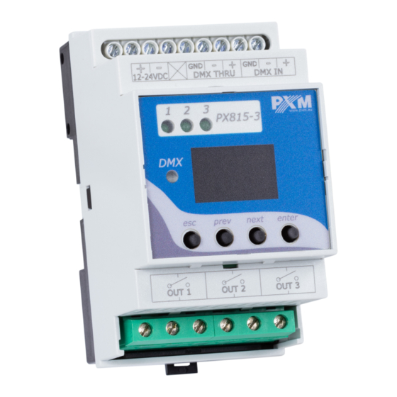
Page 6: Connectors And Control Elements
LEDs for control connectors display DMX LED programming buttons control connectors NOTE! The layout of the connectors and LED signaling in the PX815-2 may differ from the version presented in the description of the connectors and control elements above (PX815-3). -
Page 7: Designation Of Displayed Messages
Designation of displayed messages DMX address of a device – a basic item in the MENU DMX address setting no DMX signal response method selection turning on the output turning off the output maintaining the last value before the disappearance of the DMX signal channel selection device temperature... -
Page 8: Device Programming
Device programming After you switch on the module, its display shows the program version for a brief moment. To access the main menu, press enter, and the display will show Adr. Press previous or next to select the appropriate menu and press enter to confirm your selection. -
Page 9: Dmx Address
5.3 DMX address In the PX815 device menu, you can set the DMX address in groups for all output channels at once in the range 1 – 512. NOTE! If, after setting the address, the channels go beyond the DMX addressing, they will be assigned to channel 512. -
Page 10: No Dmx Signal Response
DMX signal for each channel individually. The possible options are: OFF – switching off the channel, • On – switching on the channel, • HLD – maintenance of the last DMX values. • ENTER NEXT ENTER ENTER NEXT NEXT NEXT NEXT PX815-2 version... -
Page 11: Temperature Limitation
5.5 Temperature limitation You can read the device temperature in the menu. The value is expressed in [°C]. ENTER 2 x NEXT ENTER The device has implemented switching off the device after exceeding the temperature of +80°C. Reactivation will take place after the device cools down to the temperature of +70°C. -
Page 12: Default Settings And Device Errors
5.6 Default settings and device errors If you have any difficulty accessing the device menu, e.g. it is not possible to enter a particular menu level or it is necessary to restore the device to its default settings, follow the instructions below. In the first case, when a particular menu level cannot be accessed or menu items are displayed incorrectly, this may indicate that a saving-in- memory error has occurred. -
Page 13: Restore Default Settings
+ prev – enable or disable channel 1 esc + next – enable or disable channel 2 esc + enter – enable or disable channel 3 NOTE! In PX815-2, the esc + enter key combination is not used. -
Page 14: Dmx Signal Connecting
DMX signal connecting PX815 have to be connected to DMX line in serial mode, with no branches on DMX control cable. That means the DMX line, from the signal source, must be connected to DMX IN pins of PX815 and later, directly from DMX THRU pins to the next device in DMX chain. - Page 15 List of RDM parameters supported by the PX815: Parameter name Description SUPPORTED_PARAMETERS 0x0050 all supported parameters description of additional PARAMETER_DESCRIPTION 0x0051 parameters DEVICE_INFO 0x0060 information concerning the device SOFTWARE_VERSION_LABEL 0x00C0 firmware version of the device DMX starting address of the device; DMX_ADDRESS * 0x00F0 Range 1 –...
-
Page 16: Programming
Parameter name Description setting the reaction to the NOS1_OFF/ON/HLD * 0x801D disappearance of DMX signal setting the reaction to the NOS2_OFF/ON/HLD * 0x801E disappearance of DMX signal (only in 2 and 3-channel version) setting the reaction to the NOS3_OFF/ON/HLD * 0x801F disappearance of DMX signal (only in 3-channel version) -
Page 17: Connection Scheme
16A fuse 16A 230 V AC 230 V AC (phase 1) (phase 2) receivers, e.g. lamps NOTE! The layout of the connectors and LED signaling in PX815-3 may differ from the version shown in the example connection diagram above (PX815-2). - Page 18 230 V AC receivers, e.g. lamps NOTE! The layout of the connectors and LED signaling in PX815-2 may differ from the version shown in the example connection diagram above (PX815-3). NOTE! A time interval of ~100ms has been implemented between the...
-
Page 19: Dimensions
11 Dimensions NOTE! The layout of the connectors and LED signaling in PX815-2 may differ from the version shown in the technical drawing above (PX815-3). -
Page 20: Technical Data
12 – 24V DC power consumption without load max. 2W PX815-2: 2 number of output channels PX815-3: 3 PX815-2: 16A / channel output load PX815-3: 13A / channel relay voltage max. 240V AC PX815-2: 0.5W / channel loss of power PX815-3: 0.8W / channel... - Page 21 Podłęże, 20.05.2021 DECLARATION OF CONFORMITY PXM Marek Żupnik spółka komandytowa Podłęże 654, 32-003 Podłęże we declare that our product: Product name: DMX/Relay Interface 2ch DMX/Relay Interface 3ch Product code: PX815-2 PX815-3 meets the requirements of the following standards, as well as harmonised...
Need help?
Do you have a question about the PX815-2 and is the answer not in the manual?
Questions and answers