Advertisement
Quick Links
s
RAJA + Direct Online
Controller with
WLC 3TE7131
For dependable service, it is of utmost
importance that instructions given below are
followed for selection, inspection, installation,
commissioning, operation and maintenance.
RAJA + Direct Online Controller with WLC
Selection of Controller
• Refer Table 1 for recommended selection of 3TE7 DOL
Controllers with WLC.
• 3TE7131 controllers are available from 3HP / 2.2kW to
10HP / 7.5kW suitable for Submersible pump application
motors.
11
12
4
13
7
Fig. 1: DOL Controller with WLC
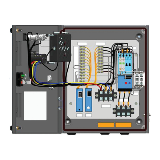
Fig. 2: DOL Controller with WLC inside view
Installation, Operation & Maintenance
Instructions
Please read and understand these instructions before
installing, operating or maintaining the equipment. Keep for
future reference.
Danger
Hazardous voltage can cause death or serious injury. Disconnect
power before working on equipment.
Warning
Automatic Motor Restart
LMRA has "Auto" mode selection. Use this function with
caution, Motor will restart automatically when healthy
power is restored back.
Reliable functioning of the equipment is only ensured with
certified components. Commissioning and maintenance by
qualified personnel only.
NOTICE
This product has been designed for environment A. Use of this product
in environment B may cause unwanted electromagnetic disturbances in
which case the user may require to take adequate mitigation measures.
Complies to standard : IS/IEC 60947-4-1
1. 'ON' push button (green)
3
2. 'OFF/RESET' push button (red)
8
3. Door knob
9
4. Metal Enclosure
5. Door
10
6. Mechanical Latch (OFF push button) to be used for
preventing undesired ON operation of Starter
1
7. Name plate
2
6
8. LED (amber) to indicate healthiness of incoming power
supply
9. Green LED to indicate Motor ON status
5
10. Rocker switch (Control ON/OFF)
11. Dual VA meter (For indication)
12. Phase Selector switch
13. Earthing screw
Advertisement

Related Manuals for Siemens RAJA+ 3TE7 DOL


Summary of Contents for Siemens RAJA+ 3TE7 DOL
- Page 1 Installation, Operation & Maintenance Instructions RAJA + Direct Online Please read and understand these instructions before installing, operating or maintaining the equipment. Keep for future reference. Controller with Danger WLC 3TE7131 Hazardous voltage can cause death or serious injury. Disconnect power before working on equipment. Warning For dependable service, it is of utmost Automatic Motor Restart importance that instructions given below are LMRA has “Auto” mode selection. Use this function with followed for selection, inspection, installation, caution, Motor will restart automatically when healthy commissioning, operation and maintenance.
-
Page 2: Installation
Installation: that the main supply is disconnected by switching off the main switch & Rocker switch. • Open the door by unscrewing the door knob. • If the relay trips even when set at rated motor current • Mount the controller on a vertical wall / plate free from the suitability of the controller/relay for the particular vibrations with proper nuts and bolts. Refer Fig. 5 for application should be checked with the nearest Siemens mounting dimensions. office. • Remove the rubber grommets for the incoming and outgoing cable connections. (Refer Fig. 2). Operation: • Connect incoming and outgoing cables as follows • Ensure the door is locked. (Refer Fig. 2): • Rotate the Mechanical Latch away from OFF push button. – Use proper cable glands to ensure dust proofing. For • Switch On the rocker switch marked ‘I’. - Page 3 5. Follow instructions given in Fig. 3 for removal of 8. Tighten the contactor terminal (T1, T2, T3) screws. relay. 9. Connect the relay terminals to Terminal block TB2. 6. Ensure that new relay hook is engaged in the slot on 10. Re-connect all the disconnected wires and check contactor. connections by referring to the wiring diagram. 7. Connect the relay terminals (L1, L2, L3) to (T1, T2, T3) (Fig. 4) of Q1 line contactor. For more Technical details like LMR-A, WLC wiring, operating Care should be taken to fix the relay terminals & sequence, mounting details etc., refer Installation & relay to contactor in the exact position shown in Troubleshooting guide no. A5E50797230A Fig. 2. Contactor outgoing terminals Hook on relay for engagement Fig. 3: Contactor – Relay connection Replacement of coil L1, L2, L3: 3φ supply Q1: Line Contactor K1: Bimetal relay K3: Line Monitoring relay...
- Page 4 Thermal Overload Back-up HRC Pump Rating Range (Amp) for Cu cable size Starter MLFB Contactor MLFB relay Fuse rating At 415V Motor / MLFB Siemens Make 3ph 50Hz Submersible type 3NA7 – HP/kW Pump 500V 3 / 2.2 3TE7131-1HC14-1A** 3TS3010-0A**-08K 3US5000-1H8K 5 – 8 5 / 3.7...
- Page 5 Ø 32 Cable entry hole Hole Dia.7mm, M6 at bottom on both side from bottom Fig. 5: Dimensional Drawing Disposal Siemens products are environment friendly, which PLASTICS: Segregate as per material type for recycling predominantly consist of recyclable materials. through authorized dealer. Because of the long lifetime of For disposals we recommend disassembling and separation Siemens Products the disposal guidelines may be replaced into following materials: by other national regulations when taking the product out of service. The local customer care service is available at any METALS: Segregate into Ferrous types for recycling through time to answer disposal-related questions. authorized dealer. Customer Care Toll free no. 1800 220 987 Email: ics.india@siemens.com Order No. A5E50548291000A/AA SACHIN ENTERPRISE Siemens Limited Product development is a continuous process. Consequently the data indicated in this Leaflet is subject to change without prior notice. For latest issue contact our sales offices.
Need help?
Do you have a question about the RAJA+ 3TE7 DOL and is the answer not in the manual?
Questions and answers